


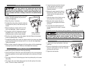
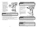
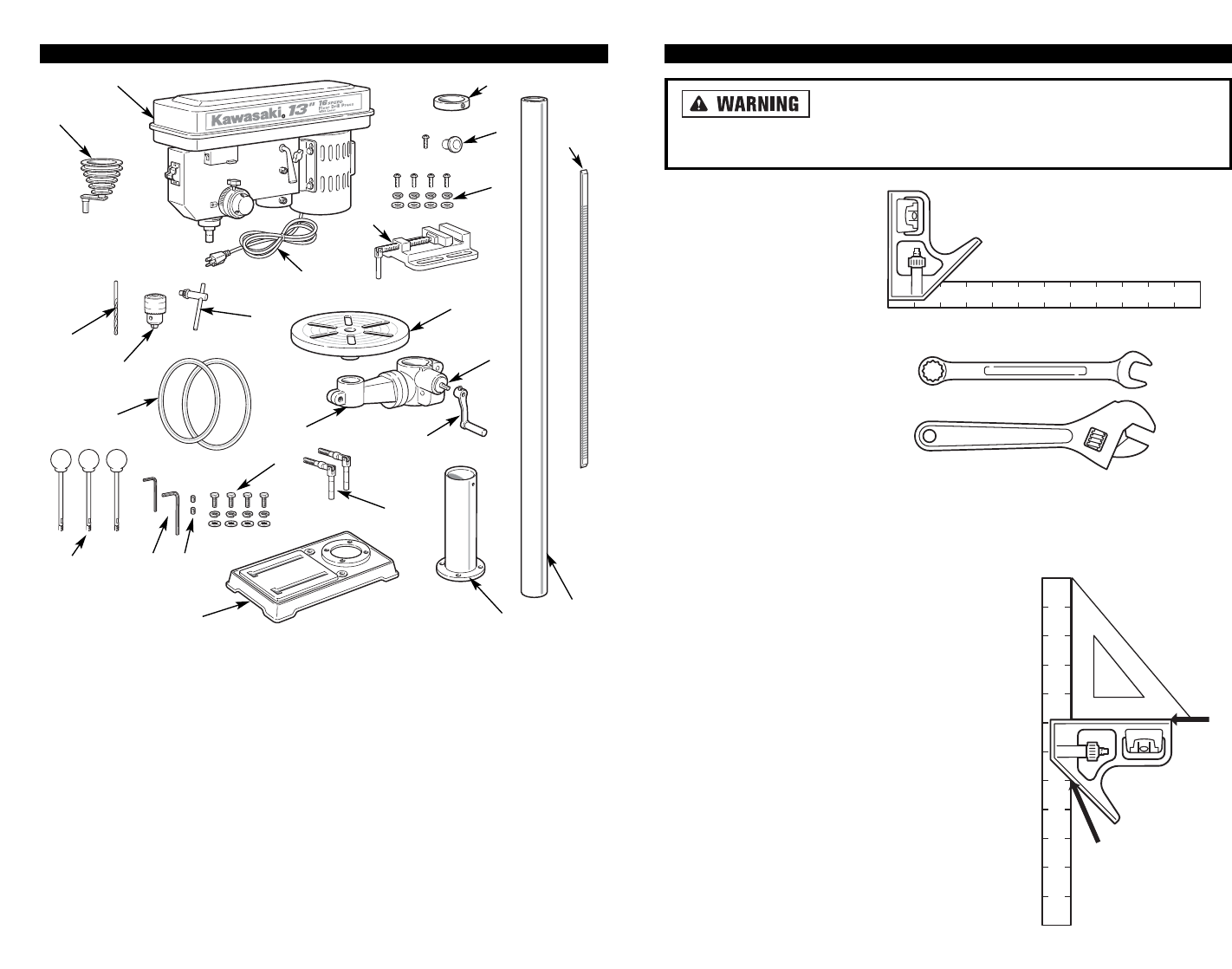
FUNCTIONAL DESCRIPTION
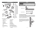
CONTROLS AND COMPONENTS:
1. Column Base
2. Column Assembly
3. Column
4. Column Rack
5. Table Crank
6. Table Support
7. Table Crank Assembly
8. Table
9. Vise
10. Vise mtg Hardware
11. Knob (and mtg Hardware)
12. Collar
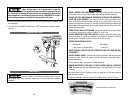
ASSEMBLY
DO NOT connect the power cord to the AC receptacle
until the drill press is completely assembled and that all cutting tools are
securely locked in the chuck.
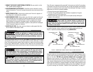
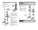
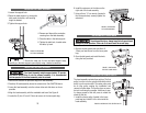
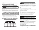
TOOLS REQUIRED FOR ASSEMBLY
The tools, pictured above, are supplied by the customer. The only requirement is
that the combination square be true. That is, the sliding ruler and the adjustable
head must form a perfect 90° angle. This can be checked by placing the square on
the corner of a right triangle. A right triangle can be
obtained from a local hardware retailer.
Place the right triangle next to the combination
square head and ruler. Loosen the thumbscrew in
the square head and adjust it to the right triangle so
there are no gaps between the triangle and the com-
bination square.
12
COMBINATION SQUARE
ADJUSTABLE WRENCH
NO GAP
NO GAP
3
2
24
1
15
16
19
20
21
22
6
7
13
9
14
8
23
10
11
12
4
17
18
5
13. Head Assembly
14. Center Pulley
15. Drill Bit
16. Drill chuck
17. Chuck Key
18. Power Cord
19. Drive Belts (2)
20. Feed Handles (3)
21. Hex (Allen) Wrenches
22. Head Assembly mtg Hardware
23. Column Assembly mtg Hardware
24. Front and Back Table Support Lock
Assemblies