


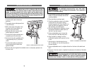
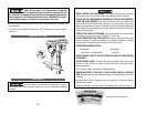
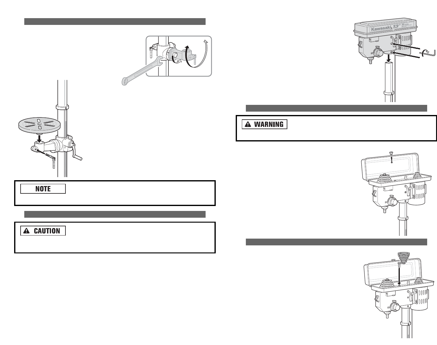
6. Install the setscrews in the holes on the
right side of the head assembly.
7. Using a 5mm “L” hex wrench (located in
the loose parts box) securely tighten the
setscrews.
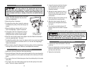
INSTALLING BELT GUARD KNOB
To avoid possible injury, always keep the belt guard closed
during drill press operation. Failure to do so could result in serous injury.
1. Remove the belt guard knob and 5mm X
12mm pan head screw from the loose parts
bag.
2. Open the belt guard and install the knob
using the hole provided.
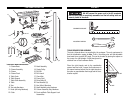
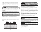
INSTALLING THE CENTER PULLEY
The head assembly contains three pulleys. The first
pulley is on the is on the spindle shaft and the third
pulley is on the motor shaft. The center pulley acts
as an idler pulley making the installation and
removal of belts easier. This pulley plays an essen-
tial role in allowing the operator a safe way to eas-
ily change speeds of the drill press to match the
needs for the job.
1. Install the center pulley (located in the loose
parts bag) and install it in the hole inside the
head assembly.
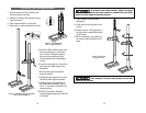
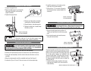
INSTALLING THE TABLE ASSEMBLY
1. Loosen the support lock.
2. Raise the table support, by turning the
table crank clockwise, until working
height is attained.
3. Tighten the support lock.
Should the table not fit into the table support freely,
carefully pry the table support open slightly using a slotted screwdriver.
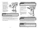
INSTALLING THE HEAD ASSEMBLY
The Head Assembly weighs approximately 55 pounds.
Use caution when lifting it onto the column assembly. It is recommended
that two people lift the head assembly onto the column.
1. Remove and discard the protective bag from head assembly.
2. Carefully lift head assembly above the column tube. See CAUTION above.
3. Lower the head assembly onto the column tube and slide down as far as
possible.
4. Align the head assembly with the worktable and base. See Figure 6.
5. Locate the (2) two 10 mm X 12mm set screws in the loose parts bag.
15
FIGURE 6. INSTALLING
THE HEAD ASSEMBLY
FIGURE 7. INSTALLING
THE BELT GUARD KNOB
FIGURE 8. INSTALLING THE CENTER PULLEY
4. Remove and discard the protective
covering from the table assembly.
5. Place the table in the table support.
6. Tighten the table lock, located under
the table, by hand.
FIGURE 5. INSTALLING
THE TABLE ASSEMBLY