


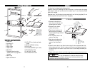
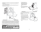
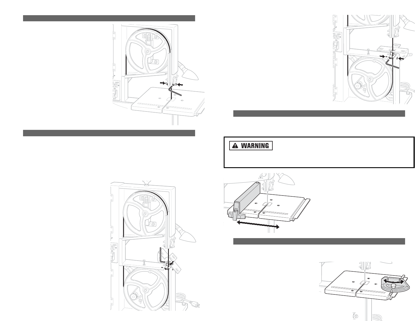
AADDJJUUSSTTIINNGG TTHHEE UUPPPPEERR GGUUIIDDEE BBEEAARRIINNGG
1. Loosen the two screws that hold the
guide pins in place using the Allen key.
2. Press the guide pins together against
the band saw blade.
3 Turn the band saw wheel by hand in a
clockwise direction several times to
bring the guide pins into position. Both
guide pins should touch the saw blade.
4. Tighten the guide pin locking screws.
5. Rotate the band saw tensioner wheel
one or two times to ensure straight
tracking of the band saw blade.
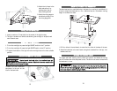
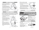
AADDJJUUSSTTIINNGG TTHHEE LLOOWWEERR BBLLAADDEE GGUUIIDDEE
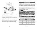
The lower blade guide has a thrust bearing that supports the band saw blade from
the rear and two guide bearings that provide lateral adjustment. These guide bear-
ings need to be adjusted after every band saw change or any tracking adjustment.
1. Tilt the work table 45 degrees to give access to the adjustment screws.
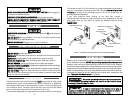
2. To adjust the thrust bearing, loosen
the thrust bearing locking screw with
the Allen wrench.
3. Adjust the bearing position until it is
1/32-inch from the band saw blade.
When adjusted correctly the band saw
blade, when turned by hand, will not
contact the thrust bearing.
4. Tighten the thrust bearing locking
screw.
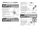
5. Open the lower housing door to
access the two screws that hold the
guide pins in place. Then, with the
table trunnion level, adjust the guide
pins by loosening the screws with the
Allen key.
NOTE: The right guide pin is accessed
through the slot in the lower housing.
6. Press the guide pins together against the
band saw blade.
7. Turn the band saw wheel by hand several
times in a clockwise direction to bring the
guide pins into the correct position. Both
guide pins should just touch the saw blade.
8. Tighten the guide pin locking screws.
9. Rotate the band wheel one or two times by
hand to ensure that the blade is not pinched.
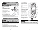
AADDJJUUSSTTIINNGG TTHHEE RRIIPP FFEENNCCEE
The rip fence attachment allows you to make parallel cuts in a piece of wood, all the
same width.
AAllwwaayyss rreemmoovvee ppoowweerr tthhee ssaaww,, bbyy ttuurrnniinngg tthhee ppoowweerr
sswwiittcchh ooffff aanndd tthheenn uunnppl
luuggggiinngg iitt,, bbeeffoorree mmaakkiinngg aannyy aaddjjuussttmmeennttss.. FFaaiilluurree ttoo
ddoo ssoo ccaann rreessuulltt iinn sseevveerree iinnjjuurryy oorr ddeeaatthh..
AADDJJUUSSTTIINNGG TTHHEE MMIITTEERR GGAAUUGGEE
The miter gauge is used to help support the work piece and can be adjusted when
cutting an angle.
1. To adjust, loosen the knob at the top
of the miter gauge.
2. Rotate the miter gauge until the
desired angle is reached.
3. Tighten the miter gauge knob to lock
the angle in position.
17
1. Adjust the rip fence to the desired
width and secure it in position using
the locking handle.
NOTE: The rip fence can be positioned on
both sides of the blade.
2. Ensure that the rip fence rests against
the wood long its entire length to pro-
duce a consistent parallel cut.
1/32" FROM BLADE