


Impinger II – 1100-000-A Series (SN 2038615 & Below) Service Manual –Int’l
16
FUSE HOLDER – REPLACEMENT
A. Shut off power at main breaker.
B. Remove control panel top and front cover.
C. Remove wires from fuse holder and mark for reassembly.
D. Remove mounting screws or mounting nut from fuse holder and remove fuse holder.
E. Reassemble in reverse order and check system operation.
THERMOSTAT, CONTROL BOX HI-LIMIT – REPLACEMENT
A. Shut off power at main breaker.
B. Remove control panel top and front cover.
C. Remove wires from thermostat and mark for reassembly.
D. Remove mounting screws and remove thermostat.
E. Reassemble in reverse order and check system operation.
NOTE: Push reset button on new thermostat.
COOLING FAN, CONTROL BOX – REPLACEMENT
A. Shut off power at main breaker.
B. Remove control panel top and front cover.
C. Remove four screws from fan frame.
D. Disconnect cord and plug from fan and remove fan.
E. Reassemble in reverse order and check system operation.
THERMOSTAT, COOLING FAN – REPLACEMENT
A. Shut off power at main breaker.
B. Remove control panel top and front cover.
C. Remove wires and mark for reassembly.
D. Remove mounting screws and remove thermostat.
E. Reassemble in reverse order and check system operation.
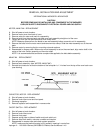
BURNER BLOWER MOTOR – REPLACEMENT
A. Shut off power at main breaker.
B. Remove control panel top and front cover.
C. Unplug motor connector.
D. Remove three mounting screws at burner housing and remove motor.
E. Remove air shutter assembly from old motor and install on new motor.
F. Reassemble in reverse order and check system operation.
NOTE: Set air shutter at approximately ½ open and adjust to get a good blue flame in high flame operation.
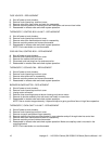
THERMOSTAT, OVEN CAVITY HI-LIMIT – REPLACEMENT
A. Shut off power at main breaker.
B. Remove control panel top and front cover.
C. Remove conveyor and bottom finger assembly.
D. Remove capillary tube from mounting bracket in oven chamber and pull through tube into control box.
E. Remove wires from thermostat and mark for reassembly.
F. Remove mounting nut and remove thermostat.
G. Reassemble in reverse order and check system operation. Make sure capillary tube is mounted in the
mounting bracket.
NOTE: Push reset button on new thermostat.