


Impinger II – 1100-000-A Series (SN 2038615 & Below) Service Manual –Int’l
18
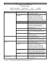
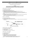
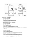
ELECTRONIC TEMPERATURE CONTROL – CALIBRATION
. Place the thermocouple of your test meter through a finger hole in the top center of the oven.
. With temperature dial fully counter clockwise, align red line on dial over the “CAL” mark on temperature scale
and tighten dial knob.
. Turn temperature dial fully clockwise, adjust pot on temperature control to achieve 575° F on temperature
meter. (There are two adjustment pots on control, adjust pot that is closest to the edge of the board.)
. Set dial to 500° F. Adjust dial to match actual temperature.
. Seal adjustment pot with glyptol or nail polish.
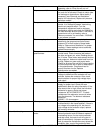
TEMPERATURE CONTROL POTENTIOMETER – REPLACEMENT
. Shut off power at main breaker.
. Remove control panel top and front cover.
. Loosen two allen screws and remove knob by sliding off shaft.
. Remove mounting nut from potentiometer shaft and remove potentiometer.
. Disconnect potentiometer wires from temperature control and mark for reassembly.
. Reassemble in reverse order and check system operation.
HEAT LIGHT – REPLACEMENT
. Shut off power at main breaker.
. Remove control panel top and front cover.
. Remove two wires from light and mark for reassembly.
. Grasp body of light and slide sideways to remove light.
. Reassemble in reverse order and check system operation.
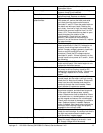
IGNITION CONTROL – REPLACEMENT
. Shut off power at main breaker.
. Remove control panel top and front cover.
. Remove front portion of control from base by releasing tabs on sides of control and pulling control from base.
. Remove wires from terminal strip on control base and mark for reassembly.
. Remove two mounting screws and remove control base.
. Reassemble in reverse order and check system operation.
GAS VALVE – REPLACEMENT AND ADJUSTMENT
. Shut off power at main breaker and disconnect gas supply.
. Disconnect gas piping from back of unit.
. Remove four screws from the incoming piping nipple mounting bracket. Remove incoming piping nipple.
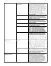
. Remove all wires from gas valve and mark for reassembly.
. Disconnect pilot tube from gas piping. Disconnect pipe union and remove gas valve.
. Remove piping from gas valve.
. Reassemble in reverse order and check system operation. Check all gas line fittings for leaks.
. Check for proper adjustment of gas pressure switch. Switch should be set as follows: 10 on dial for Nat. gas,
27 for LP or 4.5 for town gas. Adjust as needed.
. Check and adjust manifold pressure. Remove pressure tap at burner manifold and install manometer. Adjust
gas pressure as follows: 3.5” WC for Nat. gas, 10” WC for LP or 2.0” WC for town gas.
. If needed, check gas filter by removing cover plate on side of gas valve and sliding filter out of valve.
Reassemble in reverse order and check system operation. Check for gas leaks.