


Impinger II – 1100-000-A Series (SN 2038615 & Below) Service Manual –Int’l
17
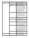
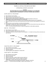
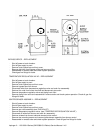
THERMOCOUPLE – REPLACEMENT
A. Shut off power at main breaker.
B. Remove control panel top and front cover.
C. Remove conveyor and bottom finger assembly.
D. Remove thermocouple from mounting bracket in oven chamber, pull through tube into control box.
E. Remove two thermocouple wires from temperature control and mark for reassembly.
F. Reassemble in reverse order and check system operation.
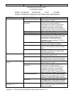
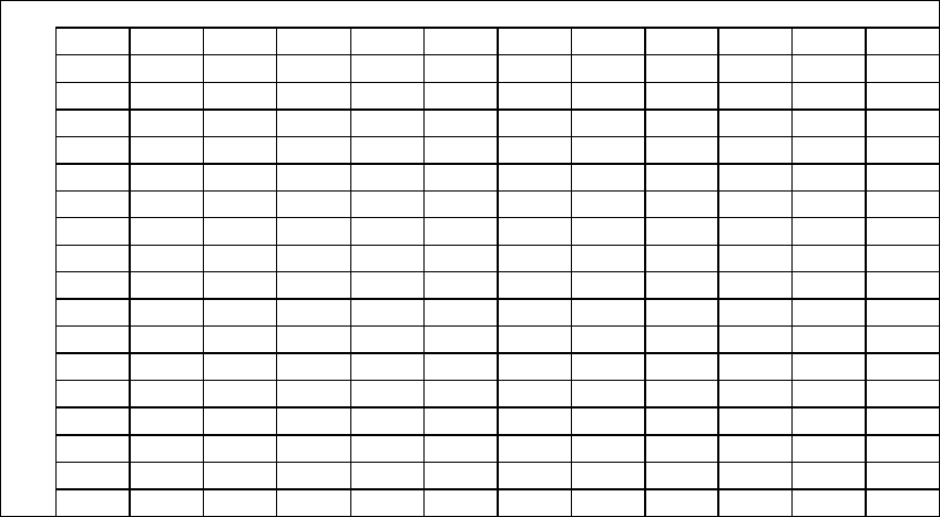
THERMOCOUPLE MEASUREMENT CHART
INFORMATION:
When two wires composed of dissimilar metals are joined together and one of the ends is heated, a
continuous current flow as generated. We use an iron constant (type J) thermocouple. The iron wire
increases the number of dissimilar junctions.
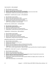
It is possible to check a thermocouple with a properly calibrated D. C. millivolt meter. At 32°F, the millivolt
reading should be 0.00. Inserting the thermocouple into an ice bath can check this.
The millivolt reading at 72°F should be 1.134.
When using the following chart, the temperature at the terminal connections must be noted. This
temperature is called the junction temperature.
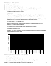
The following chart lists the thermocouple millivolt readings from 200°F to 600°F.
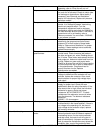
Thermocouple Measurement Chart:
Explanation: The junction temperature is the ambient air temperature where the thermocouple fastens to
the electronic temperature control board.
O V E N T E M P
200°F
250°F
300°F
325°F
350°F
400°F
425°F
450°F
500°F
550°F
600°F
J
90°F 3.26 4.77 6.30 7.06 7.83 9.37 10.14
10.91
12.46
14.00
15.53
U
88°F 3.32 4.83 6.36 7.12 7.89 9.43 10.20
10.97
12.51
14.05
15.59
N
86°F 3.37 4.88 6.41 7.17 7.94 9.49 10.26
11.03
12.57
14.11
15.65
C
84°F 3.43 4.94 6.47 7.23 8.00 9.54 10.31
11.09
12.63
14.19
15.71
T
82°F 3.49 5.00 6.53 7.29 8.06 9.60 10.37
11.14
12.69
14.23
15.76
I
80°F 3.55 5.06 6.59 7.35 8.12 9.66 10.43
11.20
12.74
14.28
15.82
O
78°F 3.60 5.11 6.64 7.40 8.17 9.72 10.49
11.26
12.80
14.34
15.86
N
76°F 3.66 5.17 6.70 7.46 8.23 9.77 10.55
11.32
12.86
14.40
15.94
75°F 3.69 5.20 6.73 7.49 8.26 9.80 10.57
11.35
12.89
14.43
15.97
74°F 3.72 5.23 6.76 7.52 8.29 9.83 10.60
11.37
12.92
14.46
15.99
72°F 3.78 5.29 6.82 7.58 8.35 9.89 10.66
11.43
12.97
14.51
16.05
T
70°F 3.83 5.34 6.87 7.63 8.40 9.95 10.72
11.49
13.03
14.57
16.11
E
68°F 3.89 5.40 6.93 7.69 8.46 10.00
10.78
11.55
13.09
14.63
16.17
M
66°F 3.95 5.46 6.99 7.75 8.52 10.06
10.83
11.61
13.15
14.69
16.23
P
64°F 4.01 5.52 7.05 7.81 8.58 10.12
10.89
11.66
13.20
14.74
16.28
62°F 4.06 5.57 7.10 7.86 8.63 10.18
10.95
11.72
13.26
14.80
16.34
60°F 4.12 5.63 7.16 7.92 8.69 10.24
11.01
11.78
13.32
14.86
16.40
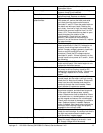
ELECTRONIC TEMPERATURE CONTROL – REPLACEMENT
. Shut off power at main breaker.
. Remove control panel top and front cover.
. Disconnect all wiring and mark for reassembly.
. Depress nylon clips and remove electronic temperature control from mounting bracket.
. Reassemble in reverse order and check system operation.