


Impinger II – 1100-000-A Series (SN 2038615 & Below) Service Manual –Int’l
21
. Remove fan shroud.
. Remove heating element(s) from oven back.
. Reassemble in reverse order and check system operation. Apply anti-seize compound to all mounting bolts
on elements and back bolts.
NOTE: Be sure all wiring connections are tight. Loose connections at on the elements may cause the
terminals to burn off and damage the elements or wiring.
CONVEYOR CONTROL POTENTIOMETER – REPLACEMENT
. Shut off power at main breaker.
. Remove control panel top and front cover.
. Loosen two allen screws and remove knob by sliding knob off of shaft.
. Remove mounting nut from potentiometer shaft and remove potentiometer.
. Disconnect potentiometer wires and mark for reassembly.
. Reassemble in reverse order and check system operation.
CONVEYOR CONTROL BOARD – REPLACEMENT
. Shut off power at main breaker.
. Remove control panel top and front cover.
. Disconnect wiring from conveyor control board and mark for reassembly.
. Remove conveyor control board from its mounting bracket.
. Reassemble in reverse order. Calibrate new conveyor control board and check system operation.
NOTE: Be sure that jumper (on conveyor control) is set to the proper input voltage (120/240) position.
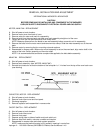
CONVEYOR CONTROL BOARD – CALIBRATION
. Connect digital voltmeter to the hall effect sensor. Black meter lead connected to black hall effect sensor lead,
red meter lead to white hall effect sensor lead.
. Turn conveyor control knob fully counter clockwise. Loosen knob and align with calibration mark and tighten
knob.
. Set conveyor control knob to the 1-minute setting. Adjust “MAX” pot on conveyor control to 327.5Hz.
. Set conveyor control knob to the 30-minute setting. Adjust “MIN” pot on conveyor control to 10.9 Hz. Recheck
at 1 minute and 30 minute settings until proper readings are achieved. Seal pots with glyptol or nail polish.
CIRCUIT BREAKER – REPLACEMENT
. Shut off power at main breaker.
. Remove control panel top and front cover.
. Disconnect two wires from circuit breaker and mark for reassembly.
. Remove mounting nut from circuit breaker and remove circuit breaker.
. Reassemble in reverse order and check system operation.
NOTE: Be sure to reset circuit breaker before operation.
CONVEYOR DRIVE MOTOR – REPLACEMENT
. Shut off power at main breaker.
. Remove control panel top and front cover.
. Remove conveyor.
. Disconnect wiring from motor and mark for reassembly.
. Remove coupling from motor drive shaft.
. Remove four mounting screws and remove conveyor motor and mounting bracket.
. Remove mounting bracket from conveyor motor.
. Reassemble in reverse order and check system operation.
REVERSING CONVEYOR DIRECTION
. Shut off power at main breaker.
. Remove control panel top and front cover.
. Reverse wires fastened to terminals A+ and A- on conveyor control board. (See schematic diagram for wire
numbers.)
. Reassemble in reverse order and check system operation.