


Impinger II – 1100-000-A Series (SN 2038615 & Below) Service Manual –Int’l
2
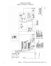
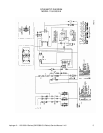
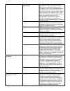
SEQUENCE OF OPERATIONS
(For serial numbers before 2038616 w/ analog control)
MODEL 1154-000-EA NAT. GAS 230 VAC 50 HZ. 1 PHASE
MODEL 1155-000-EA LP GAS 230 VAC 50 HZ. 1 PHASE
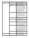
POWER SUPPLY
Electrical power to be supplied to the oven by a three conductor service.
CONTROL BOX AUTO COOL DOWN
When the temperature in the control box reaches 120° F, ± 3° (48.9°C, ± 1.7°C), the cooling fan thermostat will
switch power to the control box cooling fan. The thermostat will interrupt power to the cooling fan when the control
box temperature falls to 100° F, ± 3° (37.8°C, ± 1.7°C).
MAIN FAN CIRCUIT
Power is permanently supplied through the 10A oven fuse, through the normally closed control box hi-limit
thermostat (opens at 140° F, 60° C) to the normally open double pole oven fan switch and to the cooling fan.
Closing the oven fan switch supplies line voltage to the main fan motor. Closing the fan switch also supplies
voltage to the cooling fan. The conveyor, burner and temperature display are also energized.
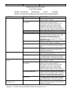
BURNER CIRCUIT
Closing the oven fan switch supplies line voltage through the normally open gas pressure switch (located in the
gas valve and closed when gas pressure is present), through the normally open air pressure switch (closed by air
pressure from the main fan), through the normally closed oven cavity hi-limit thermostat (opens at 662° F, 350°C
which is manually resettable after a drop in temperature of 18° F, 10° C), and to the ignition control.
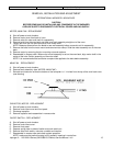
IGNITION CONTROL
The ignition control switches line voltage to the combustion blower motor, the combustion air switch switches from
normally closed to normally open upon sensing air pressure in the burner housing. After a pre-purge period of
between 30 and 60 seconds, the spark generator is energized, the main gas valve and the burner pilot light are
energized, and ignition should now occur.
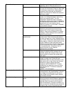
TEMPERATURE CONTROL
Closing the oven fan switch supplies line voltage to the temperature control. The 1K ohm temperature pot. is
adjusted to desired temperature. The thermocouple will provide varying millivolts to the temperature control. The
temperature control supplies line voltage to the temperature regulation valve at intermittent intervals to maintain
desired temperature. The heat lamp is energized with the temperature regulation valve.
CONVEYOR DRIVE
Closing the oven fan switch supplies line voltage to the motor control board. AC volts are converted to DC volts
and are supplied to the conveyor motor at terminals A+ and A-. Adjustment of the speed control potentiometer will
change resistance at terminals P1 and P2, varying the DC voltage to the motor. The speed of the conveyor motor
will increase or decrease as the DC voltage from the board increase or decreases respectively.
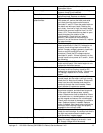
NOTE: The conveyor control uses a sensor and magnet, mounted on the conveyor motor, that senses the motor
speed. Any change in motor load (± RPM) is detected by the sensor and the voltage to the motor is adjusted
accordingly.
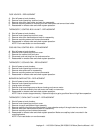
TEMPERATURE DISPLAY
Closing the switch supplies line voltage to primary of the temperature display transformer. The secondary of this
transformer supplies 12VAC to the temperature display. The thermocouple supplies DC millivolts to the
temperature display. The display converts this millivolt reading to a temperature reading.