


Impinger II – 1100-000-A Series (SN 2038615 & Below) Service Manual –Int’l
8
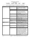
Flame sensor To check for flame sensor operation, connect a
digital multimeter (capable of measuring DC
microamps) between the flame sensor wire and
terminal #1 on the ignition control. Sensor
current is to be 3 microamps, minimum. If
these readings are not achieved, replace
igniter sensor assembly. Also, check for any
type of damage to flame sensor wire and
connections. NOTE: The DC microamp test
must be conducted with the oven in low flame
(bypass) operation.
Power supply Turn the temperature to the lowest temperature
setting. If there is sufficient microamp current,
but the flame will not stay lit, check for proper
polarity of the power supply.
Ignition control If there is sufficient flame sensor current, but
the burner will not remain ignited, check the
reset button on ignition control. If all above test
okay, replace ignition control.
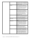
Flame will not stay on
NOTE: Flame should be lit at
this time
Temperature control Check for supply voltage at terminal #7 to L2
on temperature control. If there is no voltage,
trace wiring back to oven fan switch. Turn the
temperature adjustment knob to maximum
temperature position and check for supply
voltage at the load terminal #8 and L2. If
voltage is present and unit is not heating, refer
to “Temperature regulation valve” for next
check. If voltage is not present, proceed.
Thermocouple With power on and thermocouple leads
attached to the temperature control board:
Measure the DC millivolt output of these leads.
Refer to thermocouple chart in “removal and
installation” section for proper readings. If
these readings are not achieved, replace
thermocouple.
Temperature potentiometer Disconnect the potentiometer leads from the
temperature control board. Place ohmmeter
test leads on the blue and green pot. leads.
Reading should be 1K ohms. Place meter
leads on the blue and purple pot. leads and
rotate knob from high to low. Repeat on green
and purple leads. Check for an even rise and
fall of ohms reading to insure that there are no
open or dead spots in the potentiometer.
Check each lead to ground for any short
circuits to ground. Replace as needed.
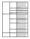
Low flame is on, but no main
flame
Temperature regulation valve If supply voltage is present on the temperature
control board at load terminals #8 and L2,
check for voltage at temperature regulation
valve. If voltage is present, listen for valve to
open and close. Also check for opens or shorts
in the operating coil. Replace as needed.
Intermittent heating Thermal overload of main fan
and burner blower motors
The main fan motor and burner blower motor
are equipped with internal thermal protection
and will cease to operate if overheating occurs.
As these motors overheat and then cool, the
burners will cycle on and off intermittently.
Improper ventilation or a lack of preventive
maintenance may cause this condition. Also,