


A-7
INSTALLATION
RANGER 275
A-7
AUXILIARY POWER RECEPTACLES,
PLUGS, AND HAND-HELD EQUIPMENT
The control panel of the Ranger 275 features three
auxiliary power receptacles: See Figure B.1.
• Two 15 amp, 120 volt duplex (double outlet) recepta-
cles.
• One 50 amp 120/240 volt single outlet receptacle.
Through these receptacles the machine can supply up
to 9,000 rated continuous watts of single-phase, 60
Hz AC power.
For further protection against electric shock, any elec-
trical equipment connected to the 120V duplex recep-
tacles must use a three-blade, grounded type plug or
an Underwriter’s Laboratories (UL) approved double
insulation system with a two-blade plug. Lincoln
offers an accessory plug kit that has the right type of
plugs. See the ACCESSORIES section of this manual
for more information.
If you need ground fault protection for hand-held
equipment refer to the K896-1 GFCI Receptacle kit in
the ACCESSORIES section of this manual for more
information.
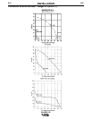
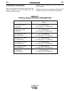
For recommended extension cord lengths and sizes
see Table A.1.
CIRCUIT BREAKERS
The Ranger 275 machines are equipped with 50 amp
circuit breakers on the 120/240 V receptacle and 15
amp circuit breakers on the 120 receptacles for over-
load protection. Under high heat a breaker may tend
to trip at lower loads than it would normally.
Never bypass the circuit breakers. Without overload
protection, the Ranger 275 could overheat and/or
cause damage to the equipment being used.
------------------------------------------------------------------------
CAUTION
PREMISES WIRING
The Ranger 275 is suitable for temporary, standby, or
emergency power using the engine manufacturer’s
recommended maintenance schedule. With its three-
wire grounded neutral generator, it can be permanent-
ly installed as a standby power unit for 240 volt, three
wire, single phase 38 ampere service.
Only a licensed, certified, trained electrician should
install the machine to a premises or residential elec-
trical system. Be certain that:
• The installation complies with the National Electrical
Code and all other applicable electrical codes.
• The premises is isolated and no feedbacking into
the utility system can occur. Certain state and local
laws require the premises to be isolated before the
generator is linked to the premises. Check your
state and local requirements.
• A double pole, double throw transfer switch in con-
junction with the properly rated double throw circuit
breaker is connected between the generator power
and the utility meter.
------------------------------------------------------------------------
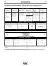
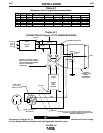
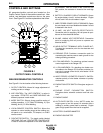
The following information and the connection diagram,
Figure A.1, can be used as a guide by the electrician
for most applications to premises wiring.
1. Install a double pole, double throw switch between
the power company meter and the premises dis-
connect. The switch rating must be the same as
or greater than the premises disconnect and
service overcurrent protection.
2. Take the necessary steps to assure that the load is
limited to the capacity of the Ranger 275 by
installing a 40 amp 240 volt double pole circuit
breaker. Maximum rated load for the 240 volt auxil-
iary is 38 amperes. Loading above 38 amperes will
reduce output voltage below the allowable -10% of
rated voltage. This may damage appliances or
other motor-driven equipment.
3. Install a 50 amp 120/240 volt plug (NEMA type 14-
50) to the double pole circuit breaker using No. 8 or
larger, 4 conductor cable of the desired length.
(The 50 amp 120/240 volt plug is available in the
optional power plug kit.
4. Plug this cable in to the 50 amp 120/240 volt recep-
tacle on the Ranger 275 case front.
WARNING