


B-3
OPERATION
B-3
RANGER 275
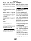
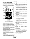
CONTROLS AND SETTINGS
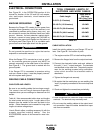
All generator/welder controls are located on the
Output Control Panel of the machine case front. Idler
control, and start/stop controls are also on the case
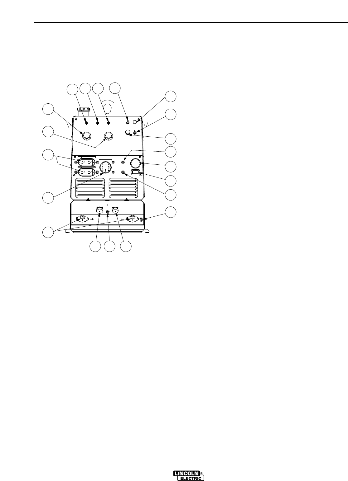
front. See Figure B.1 and the explanations that follow.
FIGURE B.1
OUTPUT PANEL CONTROLS
WELDER/GENERATOR CONTROLS
See Figure B.1 for the location of the following features:
1. OUTPUT CONTROL: Allows full range adjustment of
welding current or voltage.
2. ARC CONTROL: The “ARC CONTROL” is active in
two modes: “STICK/TIG” and “WIRE WELDING” with
different purposes in each mode.
3. MODE SWITCH: Selects three possible modes of
welding operation, 1.) CC Stick/TIG Welding, 2.) Pipe
Welding, and 3.) CV Wire Welding.
4. LOCAL/REMOTE CONTROL SWITCH: Allows the
operator to control welding output at the welding con-
trol panel or at a wire feeder, TIG amptrol, or a K857
remote control.
5. CONTACTOR SWITCH: The toggle switch labeled
“WELDING ON” and “CONTACTOR CONTROLLED”
is used to control the operation of the solid state out-
put contactor. With the switch in the “CONTACTOR
ON” position, the contactor is closed at low and high
idle.
6. BATTERY CHARGER CIRCUIT BREAKER: Opens
the engine battery circuit if a short develops. Engine
will not crank if this circuit breaker is open.
7. WIRE FEEDER POWER CIRCUIT BREAKER: Opens
the wire feeder circuit and disables the feeder if a fault
is detected in the circuit.
8. 15 AMP, 120 VOLT DUPLEX RECEPTACLES:
Connection point for supplying 120 volt power to oper-
ate one or more electrical devices.
9. 50 AMP, 120/240 VOLT RECEPTACLE: Connection
point for supplying 240 volt power to operate one
electrical device.
10. WELD OUTPUT TERMINALS WITH FLANGE NUT:
Provides the connection point for the electrode and
work cables.
11. GROUND STUD: Provides a connection point for
connecting the machine case to earth ground for the
safest grounding procedure.
12. 6 PIN AMPHENOL: For attaching optional remote
control equipment to the Ranger 275.
13. 14 PIN AMPHENOL: For attaching wire feeder con-
trol cables to the Ranger 275 (Includes contactor clo-
sure circuit, remote control circuit, wire feeder 115/42
volt power source).
14. WIRE FEEDER VOLTMETER POLARITY SWITCH:
matches polarity of wire feeder voltmeter to polarity
of electrode.
15. ENGINE RUN-STOP SWITCH: Energizes engine cir-
cuit.
16. ENGINE START PUSHBUTTON SWITCH:
Energizes starter solenoid contactor and fuel sole-
noid.
17. ENGINE CHOKE
18. AUTO IDLER SWITCH: In the “AUTO” mode, the
engine goes to low idle speed 12 seconds after a
welding or auxiliary power load is removed. Engine
goes to high speed when the load is re-applied.
19. BATTERY CHARGER AMMETER
20. ENGINE HOUR METER
5
4 3
15
17
18
16
19
20
11
121413
10
6
7
9
8
1
2