


INSTALLATION
A-7 A-7
POWER WAVE 355M/405M
Return to Section TOC Return to Section TOC Return to Section TOC Return to Section TOC
Return to Master TOC Return to Master TOC Return to Master TOC Return to Master TOC
SYSTEM DESCRIPTION
The POWER WAVE 355M/405M and Power Feed
10/11 family of products utilize a digital communication
system called Arclink. Simply put, Arclink allows large
amounts of information to be passed at very high
speeds between components (nodes) in the system.
The system requires only two wires for communication,
and because of its bus-like structure, the components
may be connected to the network in any order, thus
simplifying the system set-up.
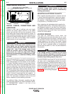
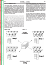
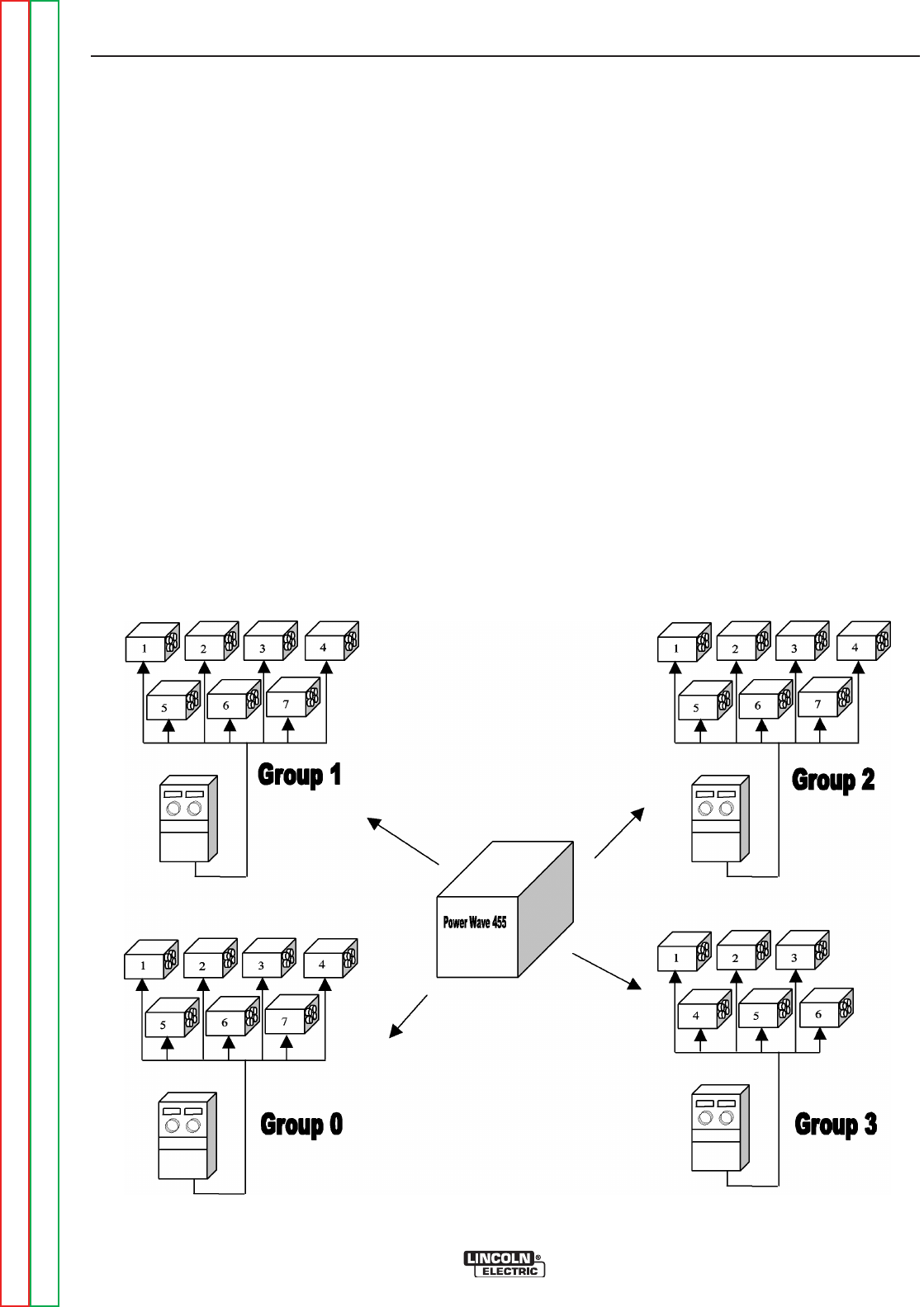
Each "system" must contain only one power source.
The power source may be connected to a maximum of
four feeder groups. Each group containing one user
interface (UI), and up to seven Feed Heads (FH). SEE
FIGURE A.1. The UI controls all of the FH’s of that
group. The UI’s and FH’s are assigned to groups by
setting a code on the DIP switches mounted on their
individual control boards. For example all of the FH’s to
be controlled by a given UI must have their "Group ID"
switches set to the same group number as the UI. In
addition, each FH must be assigned a separate FH
number within that group. See the system set-up sec-
tion for further details.
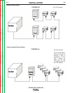
From a network perspective, each component in the
system is considered a separate node, regardless of its
physical location. For example, even though a UI and
FH may be physically mounted together, they are still
viewed as separate pieces (nodes) by the network, and
can only communicate via Arclink. The connection is
generally made externally through the Linc-Net Control
Cable, but can also be made internally, as with the PF-
10 bench model feeder.
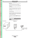
The most common Arclink configuration (called a sim-
ple system) consists of one power source, one user
interface and one feeder. Under these circumstances
the group and feed head ID DIP switches are ignored
and the system will function regardless of their posi-
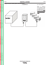
tion. The same is true for the minimum system consist-
ing of a power source and one UI (Example: a stick
welding system).
FIGURE A.1
System Model
Maximum
Configuration