


TABLE OF CONTENTS-THEORY OF OPERATION SECTION
E-1 E-1
Return to Master TOC Return to Master TOC Return to Master TOC Return to Master TOC
POWER WAVE 355M/405M
Theory of Operation . . . . . . . . . . . . . . . . . . . . . . . . . . . . . . . . . . . . . . . . . . . . . . . . . . . . . . . . . . . . . . . . . . . . .E-1
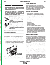
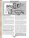
General Description ...................................................................................................................................E-2
Input Line Voltage, Auxiliary Transformer and Precharge..........................................................................E-2
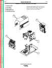
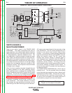
Switch Board and Main Transformer .........................................................................................................E-3
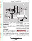
DC Bus Board, Power board and Control Board ......................................................................................E-4
Output Rectifier and Choke.......................................................................................................................E-5
Thermal Protection ...................................................................................................................................E-6
Protective Circuits......................................................................................................................................E-6
Over current Protection.......................................................................................................................E-6
Under/Over Voltage Protection ...........................................................................................................E-6
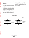
Insulated Gate Bipolar Transistor (IGBT) Operation ..................................................................................E-7
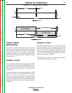
Pulse Width Modulation.............................................................................................................................E-8
Minimum/Maximum Output ................................................................................................................E-8
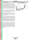
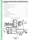
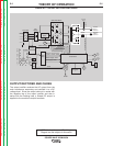
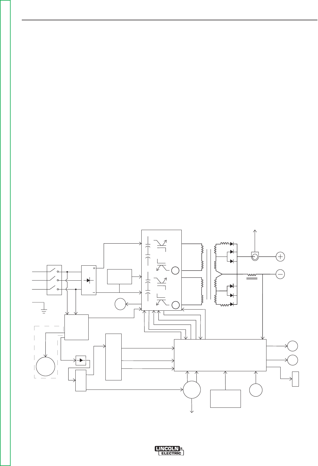
FIGURE E.1 BLOCK LOGIC DIAGRAM
Control Board
Choke
Positive
Output
Terminal
Negative
Output
Terminal
To Control
Board
Cur
r
ent
Feedbac
k
Reconnect
Switch
O
u
t
p
u
t
V
o
l
t
a
g
e
Se
n
se
Input switch
Input
Rectifier
Auxiliary
Transformer
Fan
Power
Board
220
Receptacle
RS232 Supply +5VDC
Machine Control Supply
+15VDC, -15VDC, +5VDC
40VDC
42VAC
220 VAC
Main Switch Board
115VAC Fan Supply
F
an
Co
nt
ro
l
V/F Capacitor Feedback (2)
Soft Start Control
Input Relay Control
Primary Current Feedback(2)
IGB
T D
r
i
ve
S
i
g
n
a
l
P
rimary
Current
S
ensor
Primary
C
urrent
Sensor
{
P
o
w
e
r
W
a
v
e
4
0
5
o
n
l
y
6
5
V
AC
DC
Bus
Board
Wire
Feeder
Recp.
40VDC
Can Supply +5VDC
Arc
Link
Electrode
Sense
21 Lead
Voltage
Sense
Recp.
R232
Connector
Yellow
Thermal
LED
Status
Red/Green
LED
Thermostats
2
To
Feeder