


INSTALLATION
A-14 A-14
POWER WAVE 355M/405M
Return to Section TOC Return to Section TOC Return to Section TOC Return to Section TOC
Return to Master TOC Return to Master TOC Return to Master TOC Return to Master TOC
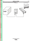
Most welding applications run with the electrode being
positive (+). For those applications, connect the elec-
trode cable between the wire feeder and the positive
(+) output Twist-Mate terminal on the power source.
Connect the other end of the electrode cable to the
wire drive feed plate. The electrode cable lug must be
against the feed plate. Be sure the connection to the
feed plate makes tight metal-to-metal electrical con-
tact. The electrode cable should be sized according to
the specifications given in the output cable connec-
tions section. Connect a work lead from the negative
(-) power source output Twist-Mate terminal to the
work piece. The work piece connection must be firm
and secure, especially if pulse welding is planned.
For additional Safety information regarding the elec-
trode and work cable set-up, See the standard "SAFE-
TY INFORMATION" located in the front of the
Instruction Manuals.
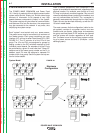
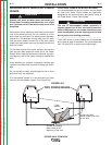
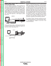
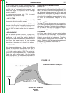
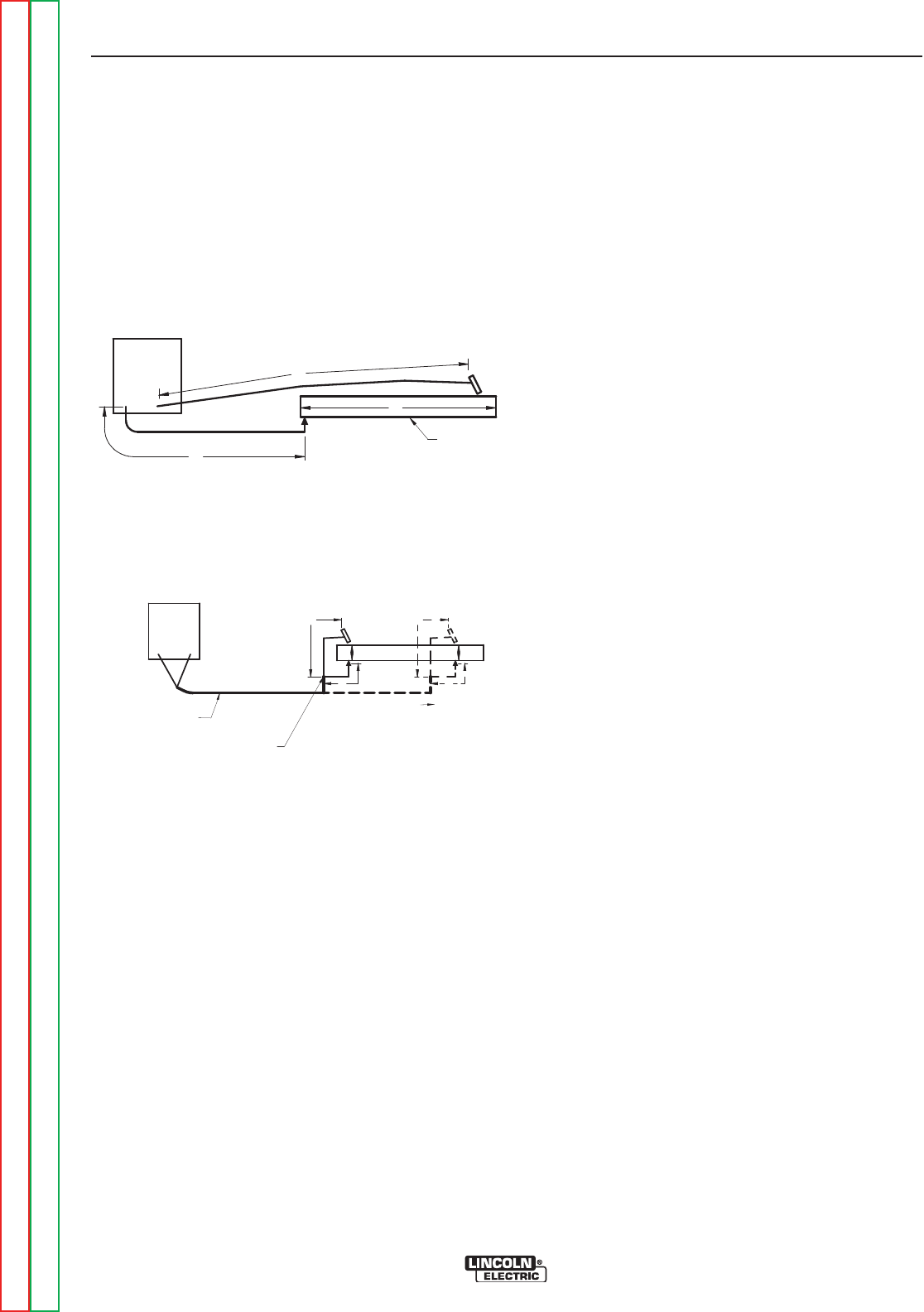
CABLE INDUCTANCE, AND ITS EFFECTS
ON PULSE WELDING
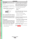
For Pulse Welding processes, cable inductance will
cause the welding performance to degrade. For the
total welding loop length less than
50 ft.(15.24m), tradi-
tional welding cables may be used without any effects
on welding performance. For the total welding loop
length greater than
50 ft.(15.24m)), the K1796 Coaxial
Welding Cables are recommended. The welding loop
length is defined as the total of electrode cable length
(A) + work cable length (B) + work length (C) (See
Figure A.3).
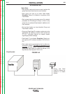
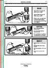
For long work piece lengths, a sliding ground should be
considered to keep the total welding loop length less
than
50 ft.(15.24m). (See Figure A.4.)
B
A
C
FIGURE A.3
POWER
WAVE
WORK
A
C
B
POWER
WAVE
FIGURE A.4
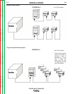
K1796 COAXIAL CABLE
MEASURE FROM END
OF OUTER JACKET OF
CABLE
C
A
B
WORK
SLIDING
WORK