


TROUBLESHOOTING AND REPAIR
F-16 F-16
POWER WAVE 355M/405M
Return to Section TOC Return to Section TOC Return to Section TOC Return to Section TOC
Return to Master TOC Return to Master TOC Return to Master TOC Return to Master TOC
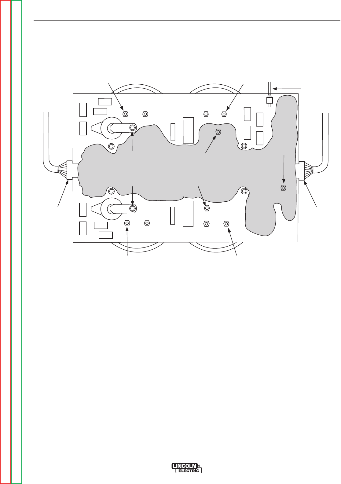
MAIN SWITCH BOARD TEST (continued)
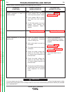
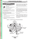
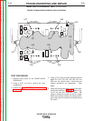
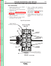
FIGURE F.2 MAIN SWITCH BOARD LEAD LOCATIONS
TEST PROCEDURE
1. Remove input power to the POWER WAVE
355M/405M.
2. Using a 5/16” nut driver, remove the case
wraparound.
3. Perform the Input Filter Capacitor Discharge
Procedure detailed earlier in this section.
4. Using a 7/16” wrench locate, label and remove
leads 201, 202, 203, 204, 205, 206, 207 and
208 from the switch board. Note lead and
washer placement for reassembly. Clear
leads.
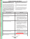
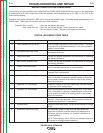
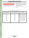
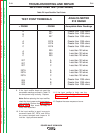
5. Using the Analog ohmmeter, perform the resis-
tance tests detailed in Table F.1. Refer to fig-
ure F.2 for test point locations. Note: Test
using an Analog ohmmeter on the Rx1 range.
Make sure the test probes are making electri-
cal contact with the conductor surfaces on the
PC board.
- +- +
- +- +
- +- + - +- +
208
201
207
209
204
205
206
203
J21
J20
J22
202
207