


TABLE OF CONTENTS - INSTALLATION SECTION
A-1 A-1
Return to Master TOC Return to Master TOC Return to Master TOC Return to Master TOC
POWER WAVE 355M/405M
Installation . . . . . . . . . . . . . . . . . . . . . . . . . . . . . . . . . . . . . . . . . . . . . . . . . . . . . . . . . . . . . . . . . . . . . . . . . . . . .A-1
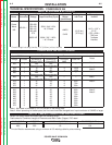
Technical Specifications 355M . . . . . . . . . . . . . . . . . . . . . . . . . . . . . . . . . . . . . . . . . . . . . . . . . . . . . . . . . .A-2
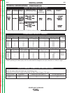
Technical Specifications 405M . . . . . . . . . . . . . . . . . . . . . . . . . . . . . . . . . . . . . . . . . . . . . . . . . . . . . . . . . .A-3
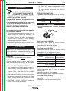
Safety Precautions .....................................................................................................................................A-4
Stacking......................................................................................................................................................A-4
Tilting..........................................................................................................................................................A-4
Input Grounding Connections....................................................................................................................A-4
Power Cord Connection.............................................................................................................................A-4
Output Cables, Connections and Limitations............................................................................................A-5
Negative Electrode Polarity........................................................................................................................A-5
Voltage Sensing..........................................................................................................................................A-5
Power Wave to Semi-Automatic Wire Feeder ...........................................................................................A-6
System Description ....................................................................................................................................A-7
System Set-up ...........................................................................................................................................A-8
Multiple Group System...............................................................................................................................A-9
Single Group Multi-Head System ............................................................................................................A-10
Welding with Multiple Power Waves ........................................................................................................A-11
Control Cable Specifications....................................................................................................................A-11
I/0 Receptacle Specifications ..................................................................................................................A-13
Dip Switch Settings and Locations..........................................................................................................A-13