


INPUT RECTIFIER REMOVAL AND REPLACEMENT (continued)
TROUBLESHOOTING AND REPAIR
F-66 F-66
POWER WAVE 355M/405M
Return to Section TOC Return to Section TOC Return to Section TOC Return to Section TOC
Return to Master TOC Return to Master TOC Return to Master TOC Return to Master TOC
PROCEDURE
1. Remove input power to the POWER WAVE
355M/405M.
2. Using a 5/16” nut driver remove the case
wraparound cover.
3. Perform the Input Filter Capacitor Discharge
Procedure detailed earlier in this section.
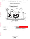
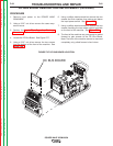
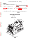
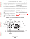
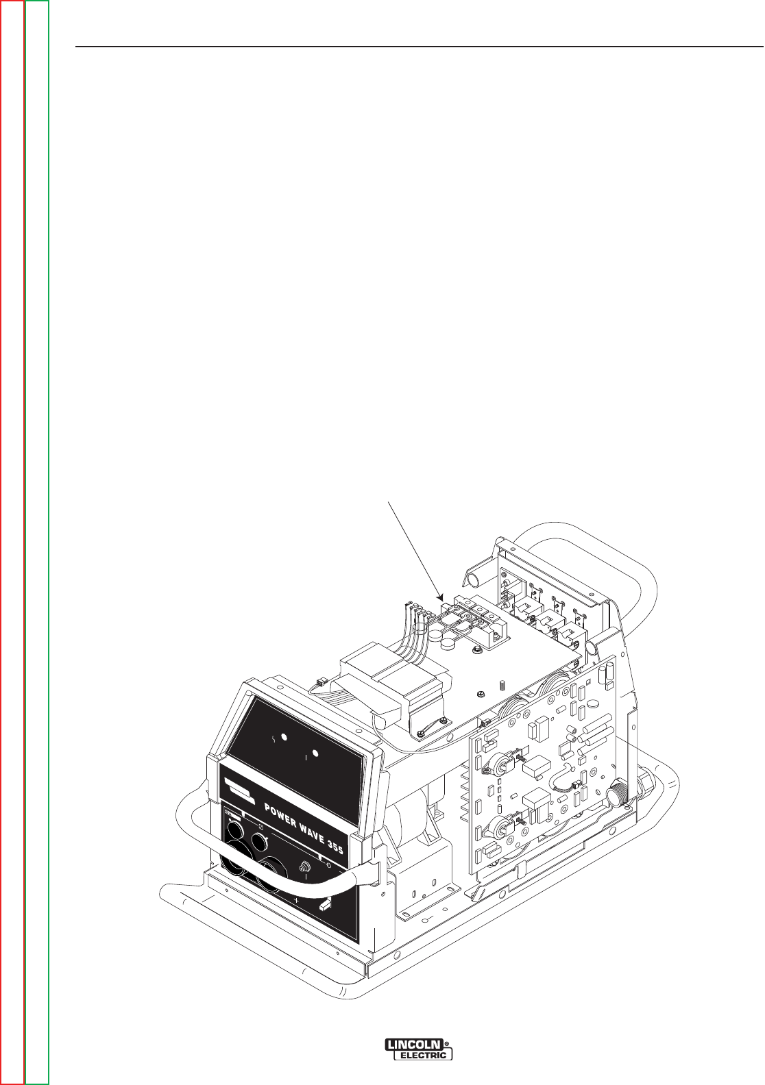
4. Locate the input rectifier. See figure F.30.
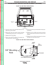
5. Carefully remove the silicon sealant insulating the
six input rectifier terminals.
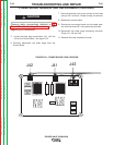
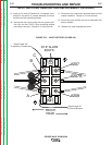
6. Remove the six screws from the terminals using a
flathead screwdriver. Carefully note the position of
all leads and their positions upon removal. See
Figure F.31.
7. Using a 3/16”in. allen wrench remove the two
mounting screws and washers from the input
bridge. See Figure F.31.
8. Remove the input bridge.
NOTE: Any instructions that are packaged with the
replacement board will supercede these
instructions.
INPUT
RECTIFIER
W
AR NI
NG
RE
M
OT
E
P
OW E
R
OF
F
ON
S
T
A
T
U
S
T
H
E
R
MA
L
L
INCO
L
N
E
L
ECT
RIC
FIGURE F.30 – INPUT RECTIFIER LOCATION