


TROUBLESHOOTING AND REPAIR
F-32 F-32
POWER WAVE 355M/405M
Return to Section TOC Return to Section TOC Return to Section TOC Return to Section TOC
Return to Master TOC Return to Master TOC Return to Master TOC Return to Master TOC
OUTPUT RECTIFIER MODULES TEST (continued)
TEST PROCEDURE
1. Remove input power to the POWER WAVE
355M/405M.
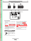
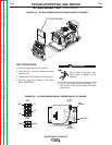
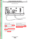
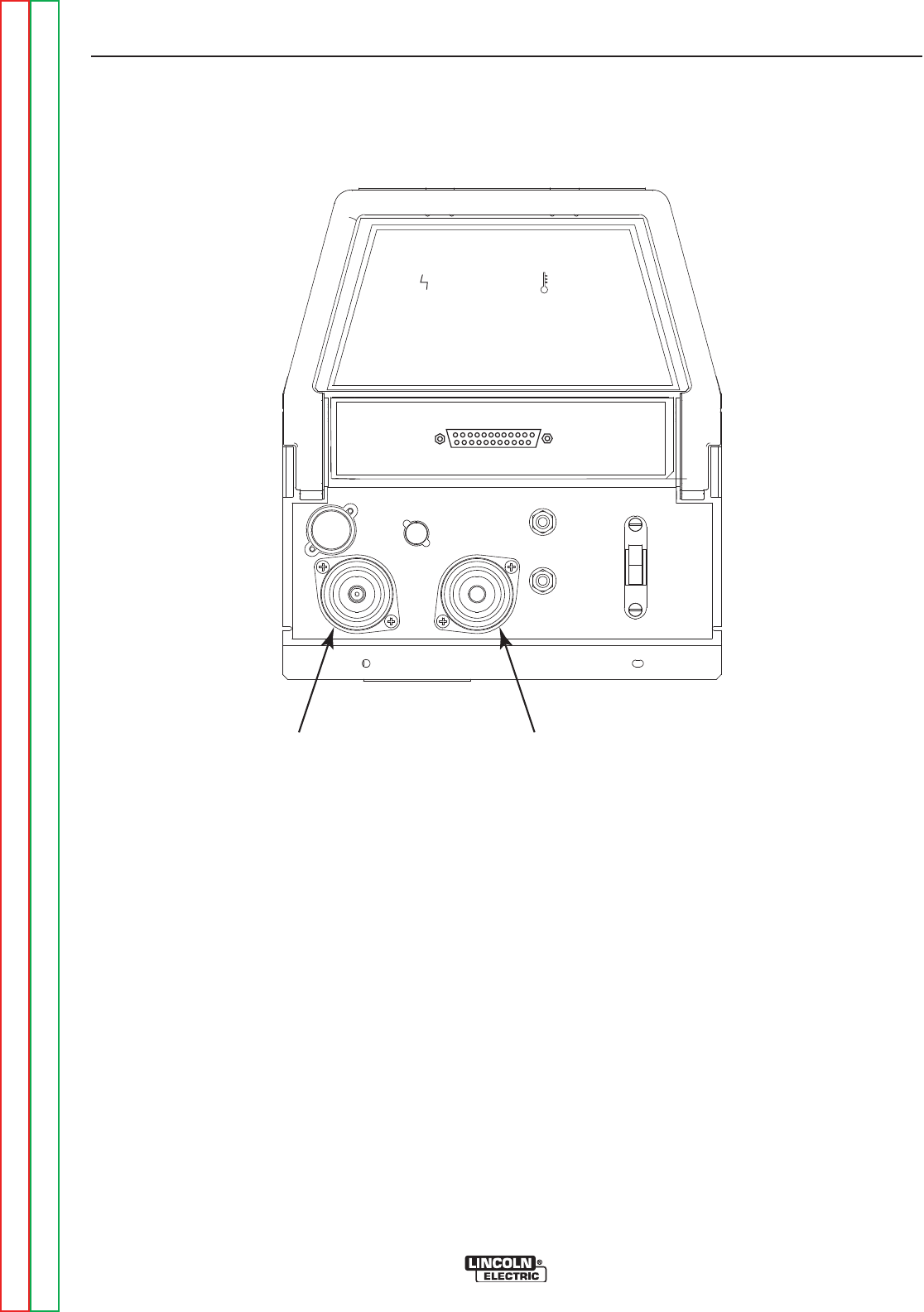
2. Locate the output terminals on the front
panel of the machine. See Figure F.7.
3. Remove any output cables and load from the
output terminals.
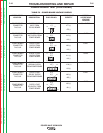
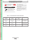
4. Using the analog ohmmeter test for more
than 200 ohms resistance between positive
and negative output terminals. Positive test
lead to the positive terminal; Negative test
lead to the negative terminal. See Figure
F.8.
NOTE: The polarity of the test leads is most
important. If the test leads polarity is not cor-
rect, the test will have erroneous results.
FIGURE F.7 Machine Output Terminals
STSTAATUSTUS THERMALTHERMAL
_
+
NEGATIVE
OUTPUT
TERMINAL
POSITIVE
OUTPUT
TERMINAL