


INSTALLATION
A-13 A-13
POWER WAVE 355M/405M
Return to Section TOC Return to Section TOC Return to Section TOC Return to Section TOC
Return to Master TOC Return to Master TOC Return to Master TOC Return to Master TOC
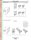
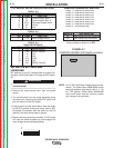
I / O RECEPTACLE SPECIFICATIONS
TABLE A.2
WIRE FEEDER RECEPTACLE
PIN LEAD# FUNCTION
A 53 Communication Bus L
B 54 Communication Bus H
C 67A Electrode Voltage Sense
D 52 +40vdc
E 51 0vdc
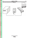
TABLE A.3
VOLTAGE SENSE RECEPTACLE
PIN LEAD# FUNCTION
3 21A Work Voltage Sense
TABLE A.4
RS232 RECEPTACLE
PIN LEAD# FUNCTION
2 253 RS232 Receive
3 254 RS232 Transmit
4#Pin5
5#Pin4
6 # # Pin20
20 # # Pin6
7 251 RS232 Common
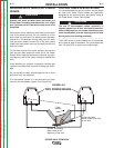
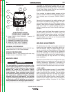
DIP SWITCH SETTINGS AND
LOCATIONS
DIP switches on the P.C. Boards allow for custom con-
figuration of the Power Wave. To access the DIP switch-
es:
1. Turn off power to the power source at the dis-
connect switch.
------------------------------------------------------------------------
2. Remove the wrap around cover from the power
source.
3. The control board is on the center assembly facing
the case front. Locate the 8-position DIP switch and
look for switch 8 of the DIP switch.
4. Using a pencil or other small object, slide the switch
to the OFF position if the work sense lead is NOT
connected. Conversely, slide the switch to the ON
position if the work sense lead is present.
5. Replace the wrap around and screws. The PC board
will “read” the switch at power up, and configure the
work voltage sense lead appropriately.
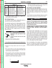
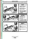
O
N
12345678
WARNING
CONTROL BOARD DIP SWITCH:
switch 1 = reserved for future use
switch 2 = reserved for future use
switch 3 = reserved for future use
switch 4 = reserved for future use
switch 5 = reserved for future use
switch 6 = reserved for future use
switch 7 = reserved for future use
switch 8* = work sense lead
switch 8*
work sense lead
off work sense lead not connected
on work sense lead connected
*Factory setting for Switch 8 is OFF.
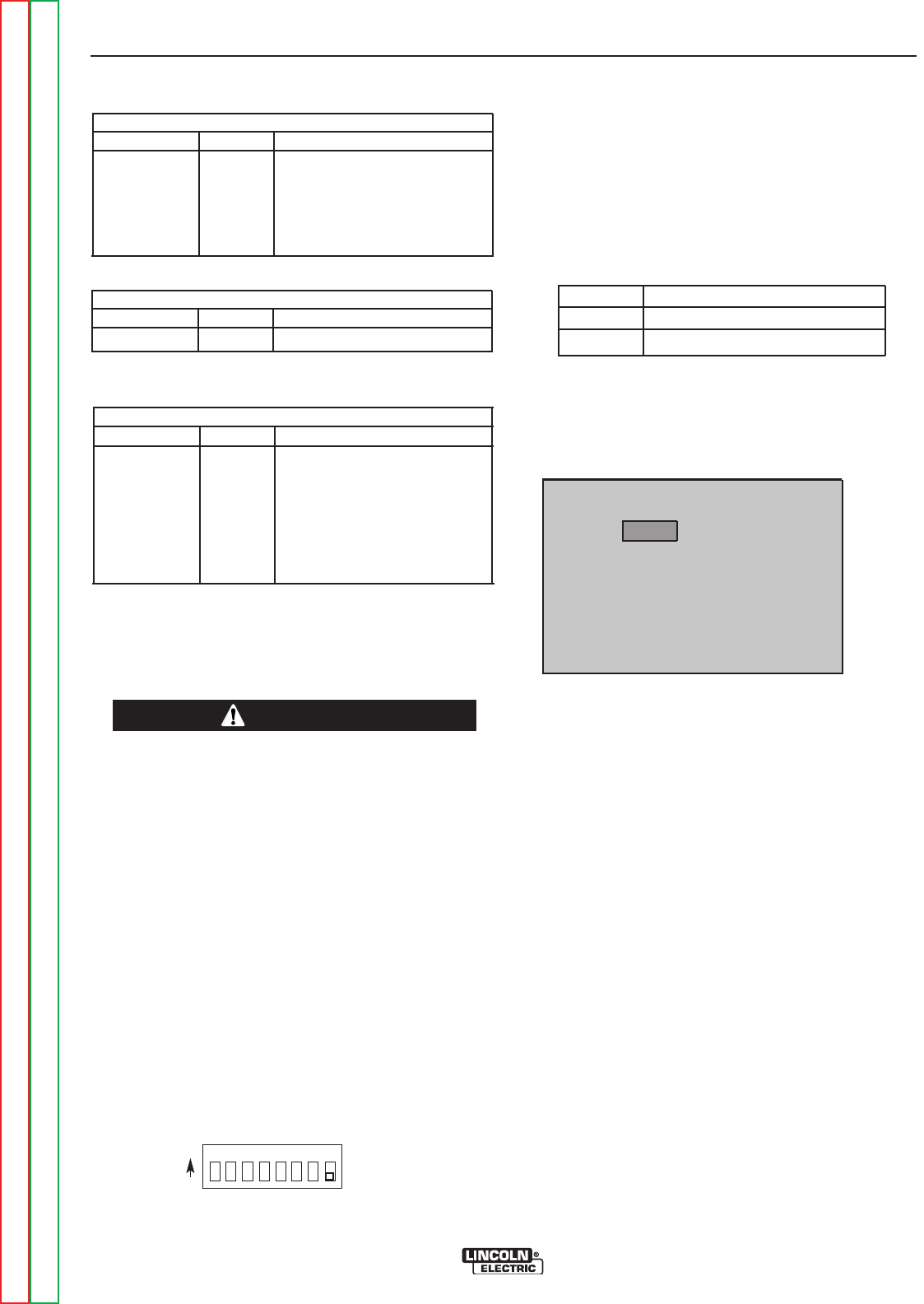
CONTROL BOARD (DIP Switch Location)
FIGURE A.7
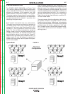
NOTE: For PF10M Dual Boom Feeder set/up and op -
eration. The Power Wave 355M/405M control
board dip switches must be set with 3, 4, 7 to
the “ON” position (Power Wave 355M/405M
input on/off switch must be cycled to enable
any change of dip switches).