


TROUBLESHOOTING AND REPAIR
F-33 F-33
POWER WAVE 355M/405M
Return to Section TOC Return to Section TOC Return to Section TOC Return to Section TOC
Return to Master TOC Return to Master TOC Return to Master TOC Return to Master TOC
OUTPUT RECTIFIER MODULES TEST (continued)
5. If 200 ohms is measured then the output
diodes are not “shorted”.
NOTE: There is a 250 ohm resistor across
the welding output terminals. See Wiring
Diagram
6. If less than 200 ohms is measured, one or
more diodes or the snubber board may be
faulty.
7. Perform the Filter Capacitor Discharge
Procedure detailed in the maintenance sec-
tion.
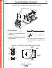
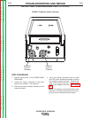
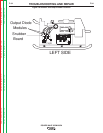
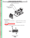
8. Locate the output diode modules and snub-
ber board. See Figure F.9.
9. Test all output diode modules individually.
Test for open diodes also.
NOTE: This may require the disassembly of
the leads and the snubber board from the
diode modules. Refer to the Output
Rectifier Modules Removal and
Replacement Procedure for detailed
instructions.
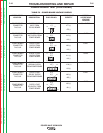
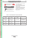
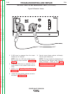
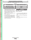
Figure F.8 Terminal Probes
_
+
- PROBE
+ PROBE