


CURRENT TRANSDUCER REMOVAL AND REPLACEMENT (continued)
TROUBLESHOOTING AND REPAIR
F-74 F-74
POWER WAVE 355M/405M
Return to Section TOC Return to Section TOC Return to Section TOC Return to Section TOC
Return to Master TOC Return to Master TOC Return to Master TOC Return to Master TOC
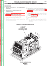
PROCEDURE
1. Remove input power to the POWER WAVE
355M/405M.
2. Using a 5/16” nut driver remove the case wrap-
around cover.
3. Perform the Input Filter Capacitor Discharge
Procedure detailed earlier in this section.
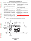
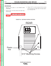
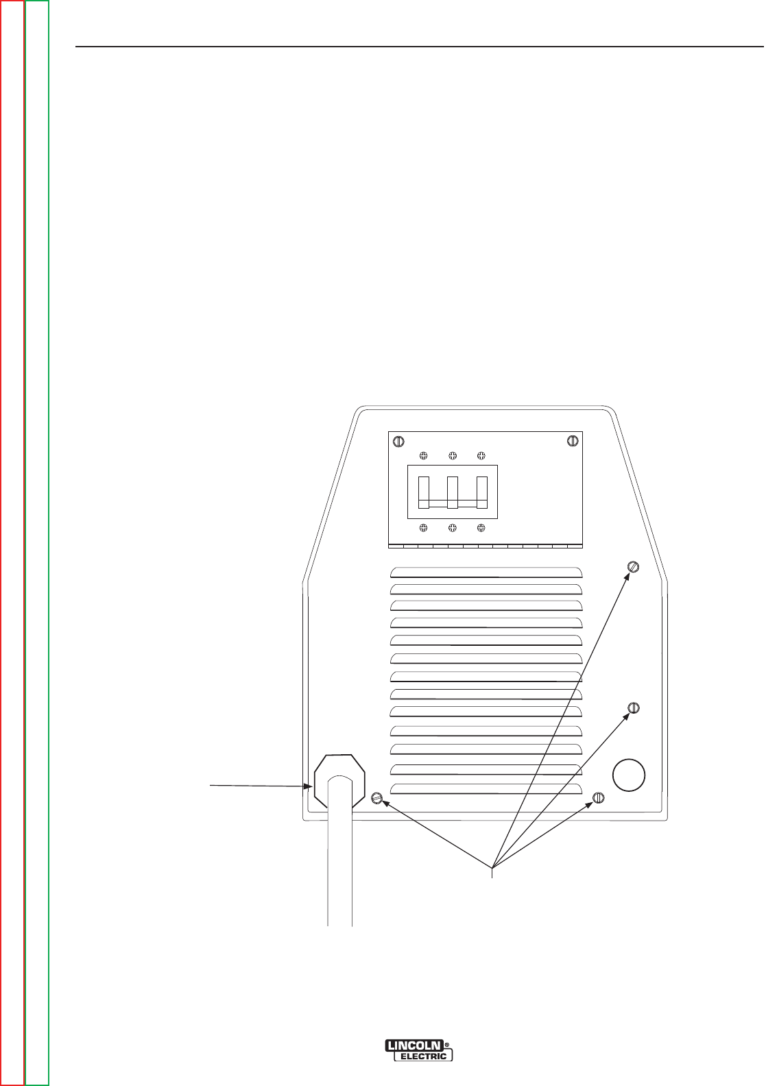
4. Using a 5/16” nut driver remove the four screws
from the bottom and right side of the rear assem-
bly. See Figure F.34.
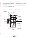
OFFOFF OFFOFF OFFO FF
Plastic
Nut
5/16" Mounting Screws
REAR
FIGURE F.34 – CASE BACK SCREW LOCATIONS