


TROUBLESHOOTING AND REPAIR
F-36 F-36
POWER WAVE 355M/405M
Return to Section TOC Return to Section TOC Return to Section TOC Return to Section TOC
Return to Master TOC Return to Master TOC Return to Master TOC Return to Master TOC
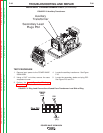
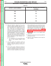
AUXILIARY TRANSFORMER TEST (continued)
TEST PROCEDURE
1. Remove input power to the POWER WAVE
355M/405M.
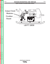
2. Using a 5/16” nut driver, remove the case
wraparound cover.
3. Perform the Input Capacitor Discharge
Procedure detailed earlier in this section.
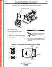
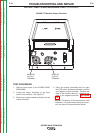
4. Locate the auxiliary transformer. See Figure
F.10.
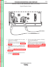
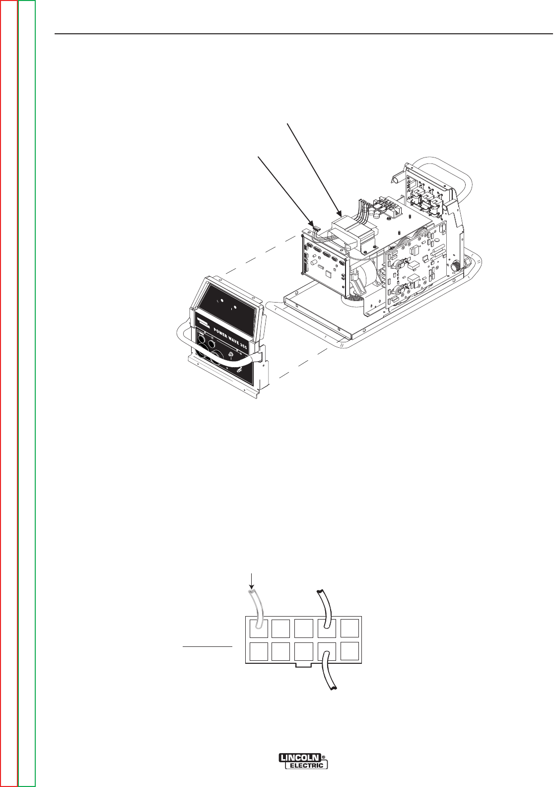
5. Locate the secondary leads and plug P52.
See Figure F.10 and F.11.
FIGURE F.10 Auxiliary Transformer
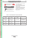
FIGURE F.11 Plug Lead Connections Viewed From Transformer Lead Side of Plug
W
A
R
N
I
N
G
R
E
M
O
T
E
P
O
W
E
R
O
F
F
O
N
Auxiliary
Transformer
Secondary Lead
Plugs P52
S
T
A
T
U
S
T
H
E
R
MA
L
L
I
N
C
O
L
N
E
L
E
C
T
R
I
C
Com 2
532
PW405
Only
(220V)
(115V)
(31)
Plug P52