


THEORY OF OPERATION
E-5 E-5
POWER WAVE 355M/405M
Return to Section TOC Return to Section TOC Return to Section TOC Return to Section TOC
Return to Master TOC Return to Master TOC Return to Master TOC Return to Master TOC
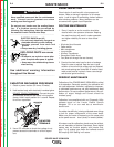
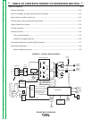
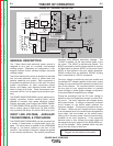
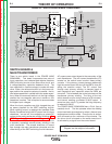
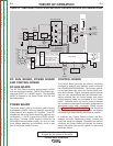
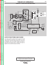
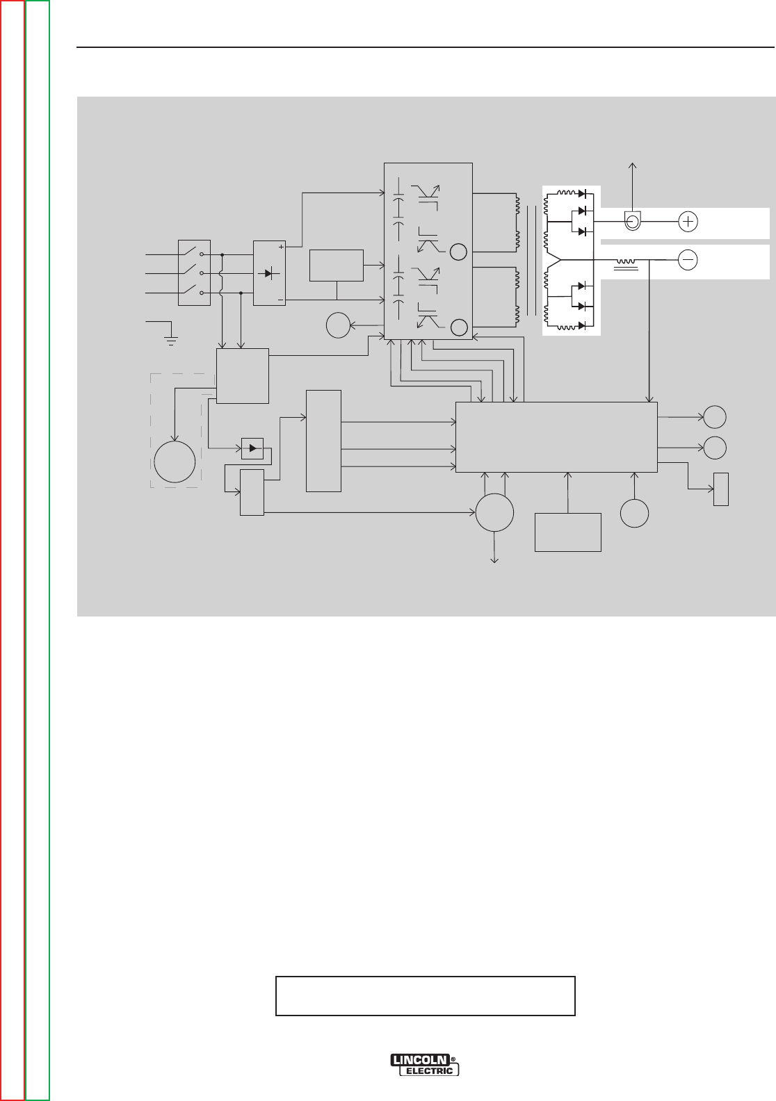
NOTE: Unshaded areas of Block Logic
Diagram are the subject of discussion
OUTPUT RECTIFIER AND CHOKE
The output rectifier receives the AC output from the
main transformer secondary and rectifies it to a DC
voltage level. Since the output choke is in series with
the negative leg of the output rectifier and also in
series with the welding load, a filtered DC output is
applied to the machine’s output terminals.
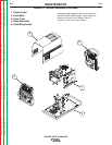
FIGURE E.5 – OUTPUT RECTIFIER AND CHOKE
C
ontrol Board
Choke
Positive
O
utput
T
erminal
Negative
O
utput
Terminal
To Control
Board
C
u
r
r
e
n
t
F
e
e
d
b
a
c
k
Reconnect
Switch
Ou
t
p
u
t
V
o
lt
a
g
e
S
e
n
s
e
Input switch
Input
Rectifier
Auxiliary
Transformer
Fan
Power
Board
220
Receptacle
RS232 Supply +5VDC
Machine Control Supply
+15VDC, -15VDC, +5VDC
40VDC
42VAC
220 VAC
M
ain Switch Board
115VAC Fan Supply
F
a
n
C
o
n
tr
o
l
V
/F Capacitor Feedback (2)
Soft Start Control
I
nput Relay Control
Primary Current Feedback(2)
IG
B
T
Drive
S
ig
n
a
l
P
rimary
Current
Sensor
Primary
Current
S
ensor
{
P
o
w
e
r
W
a
v
e
4
0
5
o
n
l
y
65VAC
DC
Bus
Board
Wire
Feeder
Recp.
40VDC
Can Supply +5VDC
Arc
L
ink
Electrode
Sense
21 Lead
Voltage
Sense
Recp.
R232
Connector
Yellow
Thermal
LED
Status
Red/Green
LED
T
hermostats
2
To
Feeder