


– 13 –
INSTALLATION
Safety Precautions
INSTALLATION OF THE SYNERGIC 7F COMPONENTS
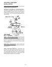
Mounting the Wire Feed Unit (K679-1 or -2)
Mount the wire feed unit by means of the insulated
mounting bracket attached to the bottom of the
gearbox. Reference L9777 dimension print at the rear
of this manual to find the size and location of the
mounting holes. The gearbox assembly is electrically
“hot” when the gun trigger is pressed. Therefore,
make certain the gearbox does not come in contact
with the structure on which the unit is mounted.
The wire feed unit should be mounted so that the
drive rolls are in a vertical plane so dirt will not collect
in the drive roll area. Position the mechanism so it will
point down at about a 45° angle so the wire feed gun
cable will not be bent sharply as it comes from the
unit.
Mounting the Control Box (K678-1)
The same control box is used for both the Synergic 7F
and Synergic 7FH wire feed units and contains two
keyhole slots and one slot for mounting. Reference
M17740 dimension print in the rear of this manual for
size and location of these slots. Mount the box at
some convenient location close to the wire feed unit
which will enable the desired control cable assembly
to reach between the control box and the wire feed
unit.
a) Drill the required holes in the mounting surface,
partially install 1/4-20 screws.
b) Open the control box door by removing the two
door screws.
c) Mount the box.
d) Tighten the screws.
e) Close the control box door and replace the door
screws.
Connecting Wire Feed Unit to Control Box
The Feeder to Control cable assemblies are available
in two types:
K680-”L” Includes a control cable with 14-pin MS-
style connectors on each end, and a 4/0
weld cable to route between the Wire
Drive and the Control Box. Available in
lengths “L” of 16ft. (4.9m) and 25ft.
(7.6m).
K681-”L” Same as K680, but does not include
weld cable. Available in lengths “L” of
12ft. (3.6m), 16ft. (4.9m) and 25ft.
(7.6m).
1. Making certain the cables are protected from any
sharp corners which may damage their jackets,
mount the cable assembly along the boom so the
end with the female MS-style connector pins is at
the wire feed unit.
2. Connect the 14-socket cable connector to the
receptacle on the back of the wire feed unit
connection box.
3. At the same end, connect the electrode lead to the
connection stud of the brass gun connection block
on the front of the wire feed unit.
4. At the control box end, connect the 14-pin
connector of the cable to the mating receptacle on
the bottom of the control box.
Electrode Routing
The electrode supply may be either from reels, Readi-
Reels, spools or bulk packaged drums or reels.
Observe the following precautions:
1. The electrode must be routed to the wire feed unit
so that the bends in the wire are at a minimum,
and also that the force required to pull the wire
from the reel into the wire feed unit is kept at a
minimum.
2. The electrode is “hot” when the gun is energized
and must be insulated from the boom and
structure.
3. If more than one wire feed unit shares the same
boom, their wire and reels must be insulated from
each other and insulated from their mounting
structure.
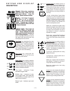
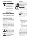
ELECTRIC SHOCK can kill.
• Do not touch electrically live parts such
as output terminals or internal wiring.
• When inching with gun trigger, electrode
and drive mechanism are “hot” to work
and ground.
• Turn OFF welding power source before
installing or changing drive roll and/or
guide tubes.
• Welding power source must be connected
to system ground per the National
Electrical Code or any applicable local
codes.
• Only qualified personnel should
perform this installation.
WARNING
Observe all additional Safety Guidelines detailed
throughout this manual.