


– 36 –
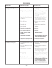
Procedure for Replacing PC Boards
Before replacing a PC board which is suspected of
being defective, visually inspect the PC board in
question for any electrical or mechanical damage to
any of its components and conductors on the back of
the board.
a. If there is no
visible damage to the PC board,
install a new one and see if this remedies the
problem. If the problem is remedied, reinstall the
old
PC board to see if the problem still exists. If it
does no longer exist with old PC board:
1. Check the PC board harness connector pins for
corrosion, contamination, or looseness.
2. Check leads in the plug harness for loose or
intermittent connection.
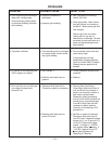
b. If PC board is visibly damaged electrically
, before
possibly subjecting the new PC board to the same
cause of failure, check for possible shorts, opens,
or grounds caused by:
1. Frayed or pinched lead insulation.
2. Poor lead termination, such as a poor contact
or a short to adjacent connection or surface.
3. Shorted or open motor leads, or other external
leads.
4. Foreign matter or interference behind the PC
boards.
c. If PC board is visibly damaged mechanically,
inspect for cause, then remedy before installing a
replacement PC board.
If there is damage to the PC board or if replacing
PC board corrects problem, return it to the local
Lincoln Electric Field Service Shop.
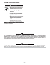
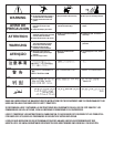
ELECTRIC SHOCK can kill.
• Have a qualified individual install and
service this equipment.
• Turn the power source input power off
at the disconnect switch before
working on this equipment.
• Do not touch electrically hot parts.
---------------------------------------------------------------------
WARNING
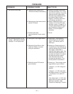
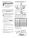
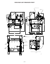
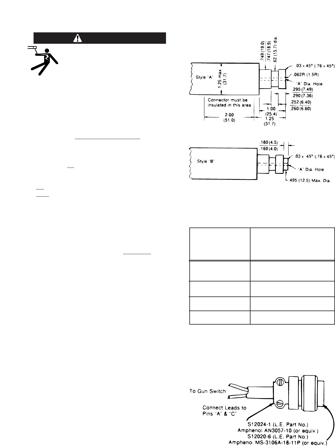
Gun Cable Connector Requirements to Permit
Proper Connection to Wire Feed Units
Connector for 1/16 - 5/64” (1.6 - 2.0 mm) Wire
Connector for .023 - .052” (19.0 / 18.9 mm) Wire
(For all other dimensions, See Diagram above).
NOTE: Connector part with .749/.747 (19.0/18,9 mm)
diameter should be made from brass if it is to be part
of the welding current carrying circuit.
“A” Diameter Hole
to be Concentric to
Wire Size
.749/.747 (19.0/18.9 mm)
in. (mm)
Diameter Within .008 (.20) F.I.M.
.068- 5/64
.125 [1/8 (3.2 mm) Drill]
(1.7-2.0)
1/16 (1.6) .078 [5/64 (2.0 mm) Drill]
.045 & .052 (1.1 & 1.3) .062 [1/16 (1.6 mm) Drill]
.023-.035 (0.6-0.9) .055 [(1.4 mm) #54 Drill]
All dimensions in inches and (millimeters)
Switch Requirements
1/2 Amp AC 24 Volts - Inductive
1/2 Amp DC 24 Volts - Inductive