


– 25 –
Making a Weld
1) Use only Power Wave model “synergic” power
sources.
2) Properly connect the electrode and work leads for
the correct electrode polarity.
3) Use Mode Selection key to set desired operating
mode. (Refer to Mode Selection section.)
4) Use Function Select and Arrow keys to set desired
Run-in and encoder knob to set Weld Feed
Speeds. (Set for each procedure if using optional
Dual Procedure Switch).
5) Adjust the voltage or percent trim, if desired, (for
each procedure if using the optional Dual
Procedure Switch) using the encoder knob in
“Volts/Trim” function (refer to Volts/Trim section).
The final setting can be adjusted according to the
desired arc voltage while welding.
6) Use Timer/Crater Select and Arrow keys to set
desired timers, or crater speed if 4-step trigger with
Crater fill has been selected. (Refer to the
Timer/Crater section).
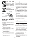
7) Feed the electrode through the gun and cable and
then cut the electrode within approximately
.38” (9.5mm) of the end of the contact tip for solid
wire, and within approximately .75” (19mm) of the
extension guide for cored wire.
8) Connect work cable to metal to be welded. Work
cable must make good electrical contact to the
work. The work must also be grounded as stated
in “Arc Welding Safety Precautions”.
9) If used, be sure shielding gas valve is turned on.
10) Position electrode over joint. End of electrode
may be lightly touching the work.
11) Lower welding helmet, close gun trigger and start
welding. Hold the gun so the contact tip to work
distance gives the correct electrical stickout as
required for the procedure being used.
12) To stop welding, release the gun trigger and then
pull the gun away from the work after the arc
goes out and Postflow time, if used, is over.
13) If necessary to optimize arc starting, adjust wire
speed acceleration, and/or Run-In speed. (See the
appropriate sections for adjusting procedures).
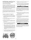
Wire Reel Changing
At the end of a coil, remove the last of the old
electrode coil from the conductor cable by either
pulling it out at the nozzle end of the gun or by using
the following procedure:
1) Cut the end of the electrode off at the gun end. Do
not break it off by hand because this puts a slight
bend in the wire making it difficult to pull it back
through the nozzle.
2) Disconnect the gun cable from the gun connector
on the Synergic 7F Wire Feed Unit and lay the gun
and cable out straight.
3) Using pliers to grip the wire, pull it out of the cable
from the connector end.
4) After the electrode has been removed, reconnect
the gun cable to the Synergic 7F.
Load a new reel of electrode per the instructions in
the Wire Reel Loading sections.
Wire Feed Overload Protection
The Synergic 7F has solid-state overload protection of
the wire drive motor. If the wire drive motor becomes
overloaded for an extended period of time, the
protection circuitry turns off the power source, wire
feed and solenoid and then displays H30. This
indicates the wire drive motor is overloaded and the
number indicates the time remaining in seconds
before the unit will automatically reset. The number
continues to decrement every second until it
reaches 0. At that time, the unit resets automatically
and the previous display will return indicating the unit
is ready to operate again. Overloads can result from
improper tip size, liner, drive rolls, or guide tubes,
obstructions or bends in the gun cable, feeding wire
that is larger than the rated capacity of the feeder or
any other factors that would impede normal wire
feeding. (See section on Avoiding Wire Feeder
Problems.)
When using an Open Arc process,
it is necessary to use correct eye,
head, and body protection
____________________________________
WARNING