


– 19 –
OPERATING INSTRUCTIONS
Safety Precautions
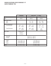
Duty Cycle
The Synergic 7F models are rated at 60% duty cycle
* for a maximum current of 600 amps.
* Based on a 10 minute time period (6 minutes on, and 4 minutes off).
KEYPAD SETUP AND OPERATION
Power-Down Save
Power to the Synergic 7F is supplied and controlled
from the power source. The Synergic 7F
automatically senses the loss of power when the
power source is turned off.
Procedure settings, including mode, crater speed,
cold feed speed , run-in speed, weld speed, timers
and acceleration are automatically saved when power
is removed. Arc Voltage setting is retained by the
synergic power source. This feature does not require
batteries and when power is restored it will
automatically return all settings to the state they were
in when power was removed. The power source may
automatically overwrite any or all of these settings
following power-up recall.
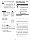
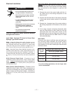
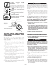
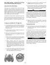
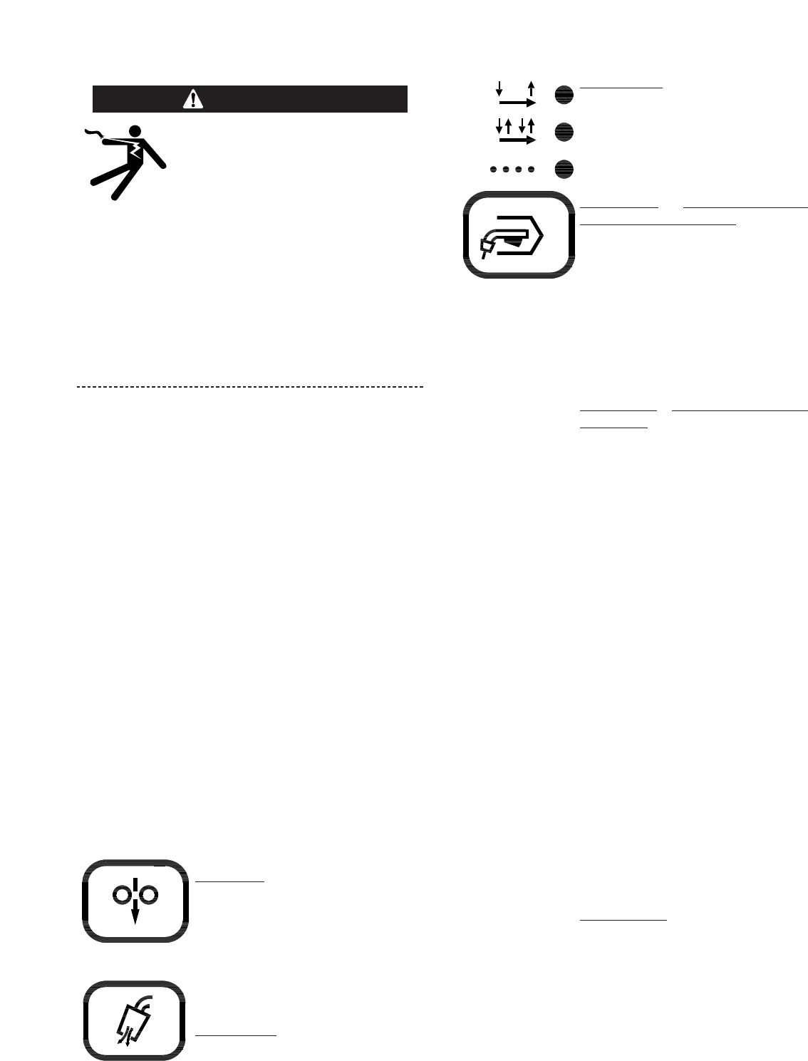
Mode Selection
Mode Select key enables operator
to choose mode of operation shown
by the indicator lights. Pressing key
causes mode lights to sequence
(top to bottom) starting from the
current indicated position.
Top Light
- Indicates 2-Step
(Standard) Trigger Mode.
1. Trigger closure energizes the
solenoid valve, then the wire feeder
and the power source after Preflow
time (See Timer/ Crater Section).
2. Releasing the trigger turns off the
wire feeder and power source and
then the solenoid valve after
Postflow time.
Middle Light - Indicates 4-Step (Lock)
Trigger Mode. These models have selectable
4-step with crater fill or, as shipped, 4-step
with current interlock. (See 4-step trigger
mode selection for method of switching).
The 4-step modes function as follows:
1. Trigger closure energizes the power
source and wirefeeder after the
preflow time.
2. Trigger release enables 4-step lock,
leaving the feeder and power source
as in step 1.
a) 4-step with current interlock will only
lock if weld current is flowing.
Breaking weld arc stops wire feed
and power source output.
b) 4-step with crater fill will lock without
welding.
3. Closing the trigger a second time
continues welding.
a) 4-step with current interlock
continues welding without changing
the settings from step 2.
b) 4-step with crater fill continues
welding but changes to the crater
settings.
4. Releasing the trigger turns off
wirefeeder and power source and
then gas solenoid after postflow
time.
Bottom Light - Indicates Spot Weld
Mode. Trigger closure energizes the
solenoid valve, then wire feeder and
the power source. The spot on timer
starts when current flows. The wire
feeder and power source then
solenoid valve are all turned off when
the spot on timer times out even
through the trigger is still closed.
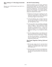
COLD FEED
GAS PURGE
Operation Keys
Cold Feed key energizes the wire
feeder but not the power source or
solenoid valve. This cold feed
speed is digitally displayed and is
adjustable (with “Arrow keys”) only
while pressing the Cold Feed Key.
The last setting is held in memory
for next Cold Inch feeding.
Gas Purge
key energizes the
solenoid valve but not the wire
feeder or power source.
STD
LOCK
SPOT
2-STEP
4-STEP
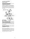
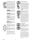
ELECTRIC SHOCK can kill.
• Do not touch electrically live parts such
as output terminals or internal wiring.
• When inching with gun trigger, electrode
and drive mechanism are “hot” to work
and ground.
• Turn OFF welding power source before
installing or changing drive roll and/or
guide tubes.
• Welding power source must be connected
to system ground per the National
Electrical Code or any applicable local
codes.
• Only qualified personnel should
perform this installation.
WARNING
Observe all additional Safety Guidelines detailed
throughout this manual.