


– 16 –
GMAW Shielding Gas
Customer must provide a cylinder of shielding gas, a
pressure regulator, a flow control valve, and a hose
from the flow valve to the gas inlet fitting of the
Synergic 7F Wire Feed Unit.
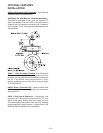
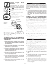
Connect a supply hose from the gas cylinder flow
valve outlet to the 5/8-18 female inert gas fitting on the
back panel of the Synergic 7F or, if used, on the inlet
of the Gas Guard regulator. (See Below).
Gas Guard Regulator - The Gas Guard Regulator is
an optional accessory (K659-1) on these models.
Install the 5/8-18 male outlet of the regulator to the
5/8-18 female gas inlet on the back panel of the
Synergic 7F. Secure fitting with flow adjuster key at
top. Attach gas supply to 5/8-18 female inlet of
regulator per instructions in the Gas Connections
Section.
CYLINDER may explode if damaged.
• Keep cylinder upright and chained to
support.
• Keep cylinder away from areas where
it may be damaged.
• Never lift welder with cylinder attached.
• Never allow welding electrode to touch cylinder.
• Keep cylinder away from welding or other live
electrical circuits.
BUILDUP OF SHIELDING GAS may
harm health or kill.
• Shut off shielding gas supply when not
in use.
SEE AMERICAN NATIONAL STANDARD Z-49.1,
“SAFETY IN WELDING AND CUTTING” PUBLISHED
BY THE AMERICAN WELDING SOCIETY.
------------------------------------------------------------------------
WARNING
Gun Cable Connections: Wire Feeder
to Gun
a. Check that the drive rolls, feeder guide tubes and
gun connector guide tube are appropriate for the
electrode size being used. If necessary, change
them per section on Wire Feed Drive Roll and
Guide Tube Kits.
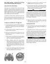
b. Connect gun to gun connector making sure all pins
and gas tube line up with appropriate holes in
connector. Tighten gun by turning large nut on gun
clockwise.
Synergic 7F Water Connections (for
Water-Cooled Guns)
The Synergic 7F models must have a K682-2 Water
Connection Kit installed. (see section under Electrical
Installation; Water Connection Kit.
1)
Using hose clamps provided with the K682-2 Kit,
connect appropriate water hoses to the coolant inlet
and outlet fittings on the back of the K682-2 Kit.
Connect the other ends of the hoses to the appropriate
ports on the water cooling units.
2)
In the event the water line fittings on your water-cooled
gun are incompatible with the female quick connects
on the front of the K682-2 Kit, male quick connects are
provided with the kit for installation on 3/16” I.D. hose
(Customer to provide appropriate clamps). The feeder
connectors self seal when
disconnected.
95 MAR