


#()!!)$#
!'O
#()!!)$# $ &*%"#)
'&*' $' '$""#
%'$(((
,''$#)'$!!$##)$#(
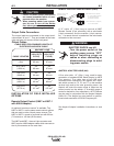
For control cable with 14-pin connector:
Connect control cable to 14-pin connector on the front
panel of the machine. See the appropriate connection
diagram for the exact instructions for the wire feeder
being used. Refer to Section 2.4.1 for connector pin
functions.
For control cable with terminal strip connectors:
The control cable from the wire feeding equipment is
connected to the terminal strips behind the control
panel*. A strain relief box connector is provided for
access into the terminal strip section. A chassis
ground screw is also provided below the terminal strip
marked with the symbol for connecting the auto-
matic equipment grounding wire. See the appropriate
connection diagram for the exact instructions for the
wire feeder being used.
A cover (Lincoln Electric Part Number S17062-3) is
available for the unused 14-pin connector to protect it
against dirt and moisture.
* See Terminal Strip Connections section for access
to the terminal strips.
$##)$#$)$!#$'!#
a) Turn off all power.
b) Place output terminals switch into the “ON” posi-
tion.
c) Connect the electrode cable to the output terminal
of polarity required by electrode. Connect the work
lead to the other terminal.
d) Place the OUTPUT CONTROL Switch at “LOCAL”
position unless a Remote Control is connected to
the DC-400.
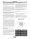
e) Place MODE SWITCH in “CONSTANT VOLTAGE
(FCAW, GMAW)”.
#$) The output terminals are energized at all
times.
"*!)%'$(((,)$##)$##
$%')$#
%*'%$(
A Multiprocess Switch has been designed for use with
the DC-400 or DC-600. With this switch installed on
the DC-400, it permits easy changing of the polarity of
the wire feed unit connected and also provides sepa-
rate terminals for connection of stick or air carbon arc.
The Multiprocess Switch is available as either a facto-
ry installed or field installed option.
#$) IF THE DC-400 IS TO BE USED FOR BOTH
SEMIAUTOMATIC/AUTOMATIC AND
STICK/
AIR CARBON ARC, THEN A MULTI-
PROCESS SWITCH IS REQUIRED.
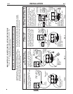
(#
The Multiprocess Switch consists of a 3-position
switch assembly that is mounted in a sheet metal
enclosure that has two output terminals on each end
of the box. The two terminals on the left side of the
box are for connection of wire feed electrode and work
leads. The two terminals on the right side of the box
are for connection of work and electrode for stick or
air carbon arc. The output terminals are protected
against accidental contact by hinged covers.
The switch mounts to the front of the DC-400 by
means of a bracket that fastens to the case sides.
Two 4/0 (107 mm
2
) leads connect the switch assem-
bly to each output stud.
$##)$#(
1. Connect wire feed unit electrode and work cables
through the rectangular strain relief holes in the
base of the DC-400 to the output studs on the left
side of the box.
2. Connect wire feeder control cable and make other
terminal strip connections as specified on the con-
nection diagram for the Lincoln wire feeder being
used. “Electrode” and “Work” are connected to the
left side of the Multiprocess Switch.
3. Connect stick or air carbon arc electrode and work
cables through the rectangular strain relief holes in
the base of the DC-400 to the output studs on the
right side of the box.
$%')$#