


)'$*!($$)#
!'O
If for any reason you do not understand the test procedures or are unable to perform the tests/repairs safely, contact your
!?31<!9>3?<>ED8?B9J5495<4(5BF935139<9DI for technical troubleshooting assistance before you proceed.
*)$#
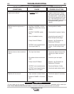
'"$)W$#)'$!W
Disconnect the remote output control and connect an
ohmmeter across 75 to 76 and rotate the rheostat in
the remote control. The resistance reading should go
from zero to 10K ohms. Repeat with ohmmeter
across 75 and 76 with same results. Connect ohm-
meter across 75 and 77. The reading should be 10K
ohms. A lower reading will indicate a shorted or par-
tially shorted rheostat. A very high reading will indi-
cate an open rheostat. In either of the last two cases,
replace rheostat. Check cable for any physical dam-
age.
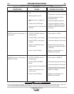
%$,'')'W'W(("!.
#W%'$*'
B94751>45F935C?<1D9?>(55D859>CDBE3
D9?>=1>E1<@1BDC<9CD6?BD855H13D<?31D9?>
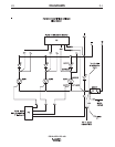
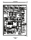
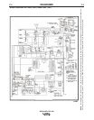
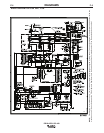
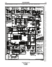
Disconnect the following leads from the bridge,
shown in Diagram 1:
a) Unplug P3 (G1, G2, G3 and 204) from the
Control PC Board.
b) Unplug P5 from the Snubber PC Board.
c) Secondary leads X1, X2, and X3 from the
anodes of the SCR’s and cathodes of the
diodes.
d) Disconnect positive bridge lead from shunt and
positive capacitor bank lead and from lug with
triple 204 leads.
e) Perform the following steps 2 and 3. If diodes
and SCR’s are not shorted, bridge test is com-
pleted. If any device appears shorted, discon-
nect the cathode lead of each diode (4 total)
and repeat Steps 2 and 3.
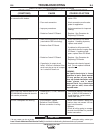
%?G5B9?45)5CD
a) Establish the polarity of the ohmmeter leads
and set to X10 scale.
b) Connect the ohmmeter positive lead to anode
and negative lead to cathode.
c) Reverse the leads of the ohmmeter from
Step b.
d) A shorted diode will indicate zero or an equally
low resistance in both directions. An open
diode will have an infinite or high resistance in
both directions and a good diode will have a
low resistance in Step b and Step a much high-
er resistance in Step c.
%?G5B(9<93?>?>DB?<<54'53D9695B)5CD
a) Connect the ohmmeter (set to m X10 scale)
leads to the anode and cathode.
b) Reverse the leads of the ohmmeter from Step
a.
c) A shorted SCR will indicate zero or an equally
low resistance in one or both directions.
d) Establish the polarity of the ohmmeter.
Connect the positive lead to the gate and the
negative lead to the cathode.
e) An open gate circuit will have an infinite or high
resistance. A good gate circuit will read a low
resistance, but not zero ohms. If gate circuit
reads zero ohms, check gate harness for
shorts between gate leads and 204 before
replacing SCR.
!)'W($ 31>;9<<
N1F51>5<53DB9391>9>CD1<<1>4C5B
F935D89C5AE9@=5>D
N)EB>D859>@ED@?G5B?661DD856EC5
2?H256?B5G?B;9>7?>5AE9@=5>D
N?>?DD?E385<53DB931<<I8?D@1BDC
,'##