


$%')$#
!'O
#'!"#('%)$#
The DC-400 is an SCR controlled three phase DC
power source. It is designed with a single range
potentiometer control.
'$""#%'$(((
&*%"#)
The DC-400 model is designed for all open arc
processes including Innershield
®
and GMAW all solid
wire and gas procedures within the capacity of the
machine, plus the capability of stick and TIG welding
and air carbon arc gouging up to 5/16” (8mm) diame-
ter. A mode switch selects CV (FCAW, GMAW), CV
Submerged Arc, or CC (Stick/TIG). Stick welding per-
formance is similar to that of the R3R-500.
The DC-400 is designed to be used with the LN-7, LN-
7 GMA, LN-8, LN-9, LN-9 GMA, LN-23P, LN-25, or
LN-742 semiautomatic wire feeders, the NA-3, NA-5
and NA-5R automatics, and the LT-56 and LT-7 trac-
tors, within the 400 ampere capacity of the machine.
The DC-400 Diode Kit option is required to utilize the
cold start and cold electrode sensing features of the
NA-3, NA-5 and NA-5R.
$%')$#!)*'(
$#)'$!(
'W')'()(
Through the unique combination of the transformer,
three phase semiconverter rectifier, capacitor bank,
arc control choke, and the solid state control system,
outstanding arc characteristics are achieved on con-
stant voltage.
In addition, an arc force control enables the DC-400 to
stick weld as well as the R3R-500.
$*)%*)$#)'$!
The OUTPUT control, a small 2 watt potentiometer, is
calibrated from 1 to 10. The OUTPUT control serves
as a voltage control in the CV position and a current
control in the CC position.
"#$*)%*)$#)'$!(,)T!$!U
$'T'"$)U
The machine output can be controlled by either the
OUTPUT control on the machine control panel, the
output control on the wire feed unit, or an optional
“remote control” that is available. This switch selects
the mode of control, either “LOCAL” or “REMOTE”.
$*)%*))'"#!(T$#U$'$*)%*))'"
#!(T'"$)U
This switch provides an alternative to the “2 to 4”
jumpering function by energizing the machine’s output
regardless of whether “2 or 4” is jumpered or not.
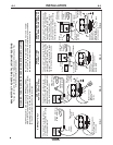
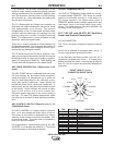
%$!').(!)$#
Polarity selection is made by appropriately connecting
the electrode and work welding cables to either the
“
“ stud or to the “” stud. Select “VOLTMETER”
switch for “
” or “” electrode, for the remote (#21)
work sensing lead.
+$!)")'(,)TU!)'$$'TU
!)'$
This switch selects electrode polarity for the remote
(#21) work sensing lead of automatic or semiautomat-
ic equipment.
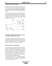
+$!)%$,'W(,)
The power input contactor operates from an auxiliary
115 volt transformer that is energized through the
POWER toggle switch on the machine control panel.
“ I “ is on and “0” is off.
%!$)!)
A white light on the machine control panel indicates
when the power source input contactor is closed. This
means the main power transformer and all auxiliary
and control transformers are energized.
)'"!%'$))$#!)
An amber light on the machine control panel indicates
when either of the two protective thermostats have
opened. Output power will be removed but input
power will still be applied to the machine.
#%*)$#))$'
The power source is equipped with an input contactor.