


$%')$#
!'O
%$,'($*'$%')$##
$#)'$!(
EDII3<51>4)9=5%5B9?4
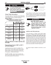
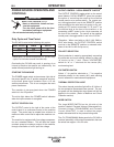
The DC-400 is rated at the following duty cycles:
* Based upon 10 minute time period (i.e., for 60% duty
cycle, it is 6 minutes on and 4 minutes off).
Overloading the DC-400 may result in opening of an
internal protective thermostat as indicated by the
amber thermal protection light turning on.
()')#)"#
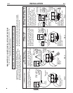
The POWER toggle switch at the extreme right side of
the control panel in the ““ position energizes and clos-
es the three phase input contactor from a 115 volt
auxiliary transformer. This in turn energizes the main
power transformer.
The machine is de-energized when the POWER
switch is in the “” position.
The white light below the POWER switch indicates
when the input contactor is energized.
$*)%*)$#)'$!!
The OUTPUT control to the right of the center of the
control panel is a continuous control of the machine
output. The control may be rotated from minimum to
maximum while under load to adjust the machine out-
put.
The machine is equipped with line voltage compensa-
tion as a standard feature. This will hold the output
constant except at maximum output of the machine,
through a fluctuation of ±10% input line voltage.
$*)%*)$#)'$!T!$!'"$)U(,)
P
The OUTPUT CONTROL toggle switch on the control
panel labeled “LOCAL-REMOTE” gives the operator
the option of controlling the output at the machine
control panel or at a remote station. For remote con-
trol, the toggle switch is set in the “REMOTE” position
and controlled at the wire feed unit control, or by con-
necting a K775 control to terminals 75, 76, and 77 on
the terminal strip at the front of the machine, or by
connecting a K857 control to the 14-pin connector on
the front of the machine. For control at the machine
control panel, the toggle switch is set in the “LOCAL”.
(Exception: When used with an LN-9, LN-9 GMA or
NA-5 wire feeder, the OUTPUT CONTROL switch
must be in the “REMOTE” position or automatic shut-
down of the LN-9 or NA-5 may occur.)
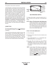
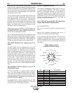
%$!').(!)$#
Polarity selection is made by appropriately connecting
the electrode and work welding cables to either the
“
” stud or to the “” stud. Select “VOLTMETER”
switch for “” or “” electrode for the remote (#21)
work sensing lead.
+$!)")'W(,)
Select “+” for positive electrode or “-” for negative
electrode polarity for the remote (#21) work sensing
lead of automatic or semiautomatic equipment.
)'"!%'$))$#!)
The amber thermal protection light will be lit if either of
the two protective thermostats have opened. The out-
put power will be disabled but input power will still be
applied to the welder. (Refer to Machine and Circuit
Protection section).
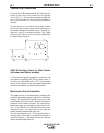
"$W(,)
The large MODE SWITCH on the left side of the
machine, labeled “Constant Voltage (Submerged Arc),
Constant Voltage (FCAW/GMAW) and Constant
Current (Stick/TIG)”, is used to select the proper
welder characteristics for the process being used.
The CV (FCAW/GMAW) Mode permits the DC-400 to
produce essentially a flat output characteristic that can
be varied from approx. 12 to 42 volts.
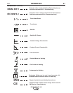
*)..! "%( +$!)(
100%
60%
50%
400
450
500
36
38
40
!)'W($ can kill.
• 1F51>5<53DB9391>9>CD1<<1>4C5B
F935D89C5AE9@=5>D
N)EB>D859>@ED@?G5B?661DD856EC5
2?H256?B5G?B;9>7?>5AE9@=5>D
N?>?DD?E385<53DB931<<I8?D@1BDC
,'##