


)'$*!($$)#
!'O
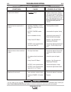
Observe all Safety Guidelines detailed throughout this manual
If for any reason you do not understand the test procedures or are unable to perform the tests/repairs safely, contact your
!?31<!9>3?<>ED8?B9J5495<4(5BF935139<9DI for technical troubleshooting assistance before you proceed.
*)$#
%'$!"(
(."%)$"(
%$((!
*(
'$""#
$*'($)$#
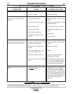
Machine has high output or pulsing
output and no control.
Machine has low output and no
control.
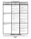
Machine does not have maximum
output.
Machine will not shut off.
1. Terminals 75, 76, or 77 grounded
to negative output.
1. OUTPUT CONTROL “LOCAL-
REMOTE” switch (S2) in wrong
position.
2. OUTPUT CONTROL switch
faulty.
3. Open in feedback circuitry.
4. Faulty Control PC Board.
5. OUTPUT control potentiometer
circuit open (lead 75).
1. One input fuse blows.
2. One phase of main transformer
open.
3. Faulty Control PC Board.
4. OUTPUT control potentiometer.
5. OUTPUT control potentiometer
leads 210, 211 or 75 open.
1. Input contactor contacts frozen.
2. Defective POWER “1/0” switch,
(S1).
1. Check 75, 76, or 77 for ground to
negative output circuit. Nearly
zero ohms to ground indicates a
grounded circuit. A value greater
than a few thousand ohms is nor-
mal. Self-restoring fuses on PC
Board automatically reset within a
few seconds after ground is
cleared.
1. Check position of switch.
2. Check switch & replace if faulty.
3. Check wiring and control PC
Board wiring harness plugs.
4. Replace. See Procedure for
Replacing PC Boards.
5. Check and replace potentiometer
if faulty. Check wiring of lead
#75.
1. Check and replace if blown after
checking for reason for blown
fuse.
2. Check for open and repair.
3. Replace. See Procedure for
Replacing PC Boards.
4. Check and Replace if faulty.
5. Check and repair broken leads.
1. Check and replace if necessary.
2. Replace.