


)'$*!($$)#
!'O
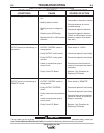
Observe all Safety Guidelines detailed throughout this manual
If for any reason you do not understand the test procedures or are unable to perform the tests/repairs safely, contact your
!?31<!9>3?<>ED8?B9J5495<4(5BF935139<9DI for technical troubleshooting assistance before you proceed.
*)$#
%'$!"(
(."%)$"(
%$((!
*(
'$""#
$*'($)$#
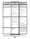
Variable or sluggish welding arc.
OUTPUT control not functioning on
the machine.
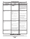
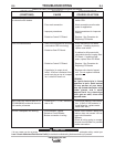
OUTPUT control not functioning on
“REMOTE” control.
1. Poor work or electrode connec-
tion.
2. Welding leads too small.
3. Welding current or voltage too
low.
4. Defective main SCR bridge.
5. Microswitch S4C or S4D actuator
defective.
1. OUTPUT CONTROL switch in
wrong position.
2. Faulty OUTPUT control switch.
3. Faulty OUTPUT control poten-
tiometer.
4. Leads or connections open in
control circuit.
5. Faulty Control PC Board.
1. OUTPUT CONTROL switch in
wrong position.
2. Faulty OUTPUT CONTROL
switch.
3. Faulty remote control potentiome-
ter.
4. Leads or connections open in
control circuit.
5. Faulty Control PC Board.
1. Check and clean all connections.
2. Check table in instruction manual.
3. Check procedures for recom-
mended settings.
4. Check and replace if defective.
5. Check and replace if defective.
(If S4C or S4D actuator is found
defective, replace mode switch
cam also.)
1. Place switch in “LOCAL”.
2. Check and replace if found faulty.
3. Check and replace if found faulty.
4. Check lead continuity and con-
nections for an open and repair if
necessary.
5. Replace. See Procedure for
Replacing PC Boards.
1. Place switch in “REMOTE”.
2. Check and replace if found faulty.
3. Check and replace if found faulty.
4. Check all leads and connections,
internal or remote, for continuity.
Repair if necessary.
5. Replace. See Procedure for
Replacing PC Boards.