


A-2
INSTALLATION
DC-400
A-2
SAFETY PRECAUTIONS
Read this entire section of operating instructions
before operating the machine.
ELECTRIC SHOCK can kill.
• Do not touch electrically live parts or
electrodes with your skin or wet
clothing.
• Insulate yourself from the work and
ground.
• Always wear dry insulating gloves.
------------------------------------------------------------------------
FUMES AND GASES can be dangerous.
• Keep your head out of fumes.
• Use ventilation or exhaust to remove
fumes from breathing zone.
------------------------------------------------------------------------
WELDING SPARKS can cause fire or
explosion.
• Keep flammable material away.
• Do not weld on containers that have
held combustibles.
------------------------------------------------------------------------
ARC RAYS can burn.
• Wear eye, ear, and body protection.
------------------------------------------------------------------------
Observe additional guidelines detailed in the
beginning of this manual.
LOCATION
The machine should be located in a clean dry place
where there is free circulation of clean air such that air
movement in through the front and out through the
back will not be restricted. Dirt and dust that can be
drawn into the machine should be kept to a minimum.
Failure to observe these precautions can result in
excessive operating temperatures and nuisance shut-
down of the machine.
DO NOT MOUNT OVER COMBUSTIBLE SURFACES.
Where there is a combustible surface directly under station-
ary or fixed electrical equipment, the surface shall be cov-
ered with a steel plate at least .06”(1.6mm) thick, which shall
extend not more than 5.90”(150mm) beyond the equipment
on all sides.
-------------------------------------------------------------------------------
INPUT POWER CONNECTIONS
By removing the rear access panel the three phase
input power is connected to the three line terminals on
the input contactor, and the earth grounding lead to
the grounding terminal on the input box floor marked
with the symbol . Install and reconnect panel for
the proper input voltage per the diagram pasted inside
the access panel cover. See Technical Data on A-1.
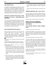
OUTPUT CABLE CONNECTIONS
The output leads are connected to the output termi-
nals marked “+” and “-”. They are located at the lower
right and lower left corners of the front panel. Strain
relief for the electrode and work cables is provided by
routing the leads through the rectangular holes in the
base before connecting them to the output terminals.
Lift the output stud cover to gain access to the output
studs. Lower stud cover after connecting output leads.
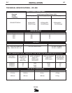
OUTPUT CABLES
Installation of Field Installed Options
CABLE SIZES FOR COMBINED LENGTH OF ELEC-
TRODE AND GROUND CABLE
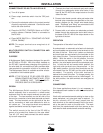
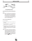
REMOTE OUTPUT CONTROL
(K857 WITH K864 ADAPTER OR K775 )
The K857 has a 6-pin MS-style connector. The K857
requires a K864 adapter cable which connects to the
14-pin connector on the machine.
An optional “remote output control” is available. This is
the same remote control that is used on the Lincoln
R3R, and DC-600 power sources (K775). The K775
consists of a control box with 28 ft (8.5m) of four con-
ductor cable. This connects to terminals 75, 76, and
77 on the terminal strip and the case grounding screw
so marked with the symbol on the machine.
These terminals are located behind the control panel
on the front of the power source. This control will give
the same control as the output control on the
machine.
CABLE
LENGTHS
UP TO 50 ft
(15m)
50 to 100 ft
(15-30 m)
100-150 ft
(30-46 m)
150-200 ft
(46-61 m)
200-250 ft
(67-76 m)
400A (100%
DUTY
CYCLE)
3/0
85 mm
(2)
3/0
85 mm
(2)
3/0
85 mm
(2)
3/0
85 mm
(2)
4/0
107 mm
(2)
500A (50%
DUTY
CYCLE)
2/0
87 mm
(2)
2/0
67 mm
(2)
3/0
85 mm
(2)
3/0
85 mm
(2)
4/0
107 mm
(2)
MACHINE LOAD
CAUTION