


A-7
INSTALLATION
DC-400
A-7
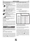
The individual case sides are removable for easy
access for internal service or inspection.
The case rear, top section, is equipped with a remov-
able access panel. This provides easy access to the
input contactor, easy connection and reconnection of
input leads, and easy access for service or inspection.
The total construction of the machine permits outdoor
operation. The enclosure is designed with air intake
louvers that keep dripping water from being drawn into
the unit. The transformer, SCR bridge assembly, and
choke are double-dipped in a special corrosion resis-
tant coating.
A permanent lifting hook is located at the top of the
machine and is positioned so that it acts as nearly as
possible through the center of gravity.
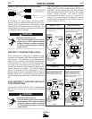
ARC FORCE SELECTOR
(Effective only on CC for Stick and TIG Processes)
An ARC FORCE selector is provided similar to that
used on the E500. This control allows the user to
select the ideal arc force for the procedure and elec-
trode being used.
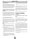
ARC CONTROL
(Effective Only When Using CVI Mode)
The ARC CONTROL is a five-position switch that
changes the pinch effect of the arc. This results in the
control of spatter, fluidity, and bead shape. The ARC
CONTROL is set to provide optimum welding depend-
ing on the process being used, position, electrode,
etc. The pinch effect is increased by turning the con-
trol clockwise and may be adjusted while the machine
is in operation.
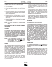
MODE SWITCH
A MODE SWITCH selects between Constant Voltage
(FCAW/GMAW), Constant Voltage (Submerged Arc),
and Constant Current (Stick/TIG).
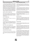
STICK WELDING
When the DC-400 is used for stick welding or air car-
bon arc, the control leads and welding cables to any
semiautomatic or automatic wire feeders must be dis-
connected from the DC-400 for maximum safety
(unless the Multiprocess switch option is installed).
PARALLELING
There are no provisions on the DC-400 to permit par-
alleling.
DIODE OPTION
The DC-400 Diode option is required to utilize the cold
start and cold electrode sensing features of the NA-3,
NA-5 or NA-5R. When this option is not used with an
NA-3, NA-5 or NA-5R, see the DC-400/NA-3, DC-
400/NA-5 or DC-400/NA-5R connection diagram for
instructions on how to disable this circuit. If the circuit
is not disabled, the wire cannot be inched down.
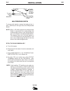
Machine & Circuit Protection
(Thermal Protection Light)
The power source is thermostatically protected with
proximity thermostats against overload or insufficient
cooling. One thermostat is located on the nose of the
center bottom primary coil and a second thermostat is
attached to the lead connecting the secondaries.
Both thermostats are connected in a series with the 2-
4 circuit. If the machine is overloaded, the primary
thermostat will be open, the output will be zero, and
the amber thermal protection light will be on. The fan
will continue to run. The secondary thermostat will
open either with an excessive overload or insufficient
cooling. The output will be zero and the amber pro-
tection light will be on. When the thermostats reset
the protection light will be off.
The power source is also protected against overloads
on the SCR bridge assembly through an electronic
protection circuit. This circuit senses an overload on
the power source and limits the output to 550 amps by
phasing back the SCR’s.
Protection is provided to protect the circuitry from
accidental grounds. If the customer accidentally
“grounds” 75, 76, or 77 to the positive output lead, the
DC-400 will be reduced to a low value, thus prevent-
ing any damage to the machine. If the ground occurs
between 75, 76, 77 and the negative output lead, one
of the PC board “self-restoring” fuses will blow, pre-
venting any machine damage.