


B-6
OPERATION
B-6
POWER SOURCE OPERATION
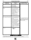
Duty Cycle and Time Period
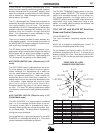
The DC-400 is rated at the following duty cycles:
* Based upon 10 minute time period (i.e., for 60% duty
cycle, it is 6 minutes on and 4 minutes off).
Overloading the DC-400 may result in opening of an
internal protective thermostat as indicated by the
amber thermal protection light turning on.
STARTING THE MACHINE
The POWER toggle switch at the extreme right side of
the control panel in the “I“ position energizes and clos-
es the three phase input contactor from a 115 volt
auxiliary transformer. This in turn energizes the main
power transformer.
The machine is de-energized when the POWER
switch is in the “0” position.
The white light below the POWER switch indicates
when the input contactor is energized.
OUTPUT CONTROL DIAL
The OUTPUT control to the right of the center of the
control panel is a continuous control of the machine
output. The control may be rotated from minimum to
maximum while under load to adjust the machine out-
put.
The machine is equipped with line voltage compensa-
tion as a standard feature. This will hold the output
constant except at maximum output of the machine,
through a fluctuation of ±10% input line voltage.
OUTPUT CONTROL “LOCAL-REMOTE” SWITCH
©
The OUTPUT CONTROL toggle switch on the control
panel labeled “LOCAL-REMOTE” gives the operator
the option of controlling the output at the machine
control panel or at a remote station. For remote con-
trol, the toggle switch is set in the “REMOTE” position
and controlled at the wire feed unit control, or by con-
necting a K775 control to terminals 75, 76, and 77 on
the terminal strip at the front of the machine, or by
connecting a K857 control to the 14-pin connector on
the front of the machine. For control at the machine
control panel, the toggle switch is set in the “LOCAL”.
(Exception: When used with an LN-9, LN-9 GMA or
NA-5 wire feeder, the OUTPUT CONTROL switch
must be in the “REMOTE” position or automatic shut-
down of the LN-9 or NA-5 may occur.)
POLARITY SELECTION
Polarity selection is made by appropriately connecting
the electrode and work welding cables to either the
“
+” stud or to the “-” stud. Select “VOLTMETER”
switch for “+” or “-” electrode for the remote (#21)
work sensing lead.
VOLTMETER SWITCH
Select “+” for positive electrode or “-” for negative
electrode polarity for the remote (#21) work sensing
lead of automatic or semiautomatic equipment.
THERMAL PROTECTION LIGHT
The amber thermal protection light will be lit if either of
the two protective thermostats have opened. The out-
put power will be disabled but input power will still be
applied to the welder. (Refer to Machine and Circuit
Protection section).
MODE SWITCH
The large MODE SWITCH on the left side of the
machine, labeled “Constant Voltage (Submerged Arc),
Constant Voltage (FCAW/GMAW) and Constant
Current (Stick/TIG)”, is used to select the proper
welder characteristics for the process being used.
The CV (FCAW/GMAW) Mode permits the DC-400 to
produce essentially a flat output characteristic that can
be varied from approximately. 12 to 42 volts.
DC-400
DUTY CYCLE * AMPS VOLTS
100%
60%
50%
400
450
500
36
38
40
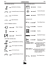
ELECTRIC SHOCK can kill.
• Have an electrician install and service
this equipment.
• Turn the input power off at the fuse
box before working on equipment.
• Do not touch electrically hot parts.
---------------------------------------------------------------------
WARNING