


vi
vi
TABLE OF CONTENTS
Page
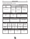
Installation .. .......................................................................................................Section A
Technical Specifications ............................................................................................. A-1
Safety Precautions.......................................................................................................A-2
Location........................................................................................................................A-2
Input Power Connection...............................................................................................A-2
Output Connections .....................................................................................................A-2
Output Cables ..............................................................................................................A-2
Remote Output Control ................................................................................................A-2
Remote Control Adapter Cable (K864) ........................................................................A-3
Amptrol Adapter Cable (K843).....................................................................................A-3
(K843)Amptrol Adapter Installation Instructions...........................................................A-3
Hi-Frequency Kit ..........................................................................................................A-4
Amptrol Adapter for K799 Hi-Frequency Kit.................................................................A-4
Multiprocess Switch .....................................................................................................A-4
Capacitor Discharge Circuit .........................................................................................A-4
Undercarriages.............................................................................................................A-4
Installation of Equipment Required for Recommended Processes .................A-4 thru A-6
Connection of DC-400 to LN-22 or LN25.....................................................................A-5
Auxiliary Power Connections .......................................................................................A-6
Remote Control Connections.......................................................................................A-6
Output Connections .....................................................................................................A-6
Input Connections ........................................................................................................A-6
Input Line Voltage Compensation................................................................................A-6
Solid State Output Control ..........................................................................................A-6
Solid State Control System ..........................................................................................A-6
Machine Cooling ..........................................................................................................A-6
Case Features .............................................................................................................A-6
Arc Force Selector .......................................................................................................A-7
Arc Control ...................................................................................................................A-7
Mode Switch.................................................................................................................A-7
Stick Welding ...............................................................................................................A-7
Paralleling ....................................................................................................................A-7
Diode Option ................................................................................................................A-7
Machine & Circuit Protection........................................................................................A-7
Multiprocess Switch .....................................................................................................A-8
________________________________________________________________________
Operation ...........................................................................................................Section B
Safety Precautions ..................................................................................................... B-1
Meanings of Graphic Symbols .......................................................................B-1 thru B-4
General Machine Description.......................................................................................B-5
Recommended Processes and Equipment...... ...........................................................B-5
Operational Features & Controls ...........................................................................B-5
Power Source Operation..........................................................................B-6 thru B-8
________________________________________________________________________
Accessories .. .....................................................................................................Section C
Factory or Field Installed Options ................................................................................C-1
Diode Option..........................................................................................................C-1
Multi-Process Switch ............................................................................................C-1
Field Installed Options .................................................................................................C-1
Remote Output Control..........................................................................................C-1
Amptrol Adapter Cable ..........................................................................................C-1
Remote Control Adapter Cable ............................................................................C-1
Multi-Process Switch ............................................................................................C-1
Capacitor Discharge Circuit...................................................................................C-1
Hi-Frequency Kit....................................................................................................C-2
Optional Amptrol Adapter for Hi-Frequency Kit .....................................................C-2
Undercarriages......................................................................................................C-2
________________________________________________________________________