


A-6
INSTALLATION
DC-400
A-6
AUXILIARY POWER CONNECTIONS
The power source is equipped to furnish nominally
110-115 volt AC and 40-42 volt AC auxiliary power for
operating wire feeding equipment, etc. The auxiliary
power is available at the 14-pin MS-style connector
receptacle on the control panel and/or at a terminal
strip behind the hinged control panel on the front of
the power source. 110-115V AC is available at recep-
tacle pins A and J (Domestic and Export models only),
terminals 31 and 32 (all models) and at duplex recep-
tacle. 40-42V AC is available only at receptacle pins I
and K. The 110-115V AC and the 40-42V AC are iso-
lated circuits and each is protected by circuit breakers,
15 amp on 115VAC circuit, and 10A on 42 Vac circuit.
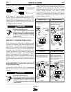
REMOTE CONTROL CONNECTIONS
Remote control connections are available both at a
14-pin connector receptacle located on the control
panel, and on terminal strips with screw connections
located behind the hinged control panel on the front of
the power source.
OUTPUT CONNECTIONS
The output terminals are recessed on the case front
and labeled “+” and “-”.
INPUT CONNECTIONS
The three input lines are brought in through the rear
panel of the power source and attached to the input
contactor. Removal of the removable access panel
makes the contactor accessible for the input cable
connections.
INPUT LINE VOLTAGE COMPENSATION
The power source is equipped with input line voltage
compensation as standard. For a line voltage fluctua-
tion of ±10% the output will remain essentially con-
stant. This is accomplished through the feedback net-
work in the control circuit.
SOLID STATE OUTPUT CONTROL
The output of the welder is electronically controlled by
SCR’s instead of mechanical contactors, providing
extra long life for highly repetitive welding applica-
tions.
SOLID STATE CONTROL SYSTEM
The control circuitry consists of six basic circuits: (1)
the SCR snubber network, (2) the SCR firing circuit,
(3) the control/fault protection circuit, (4) the starting
circuit, (5) the power-up delay circuit, and (6) the
power circuit.
The SCR snubber board consists of a capacitor and
resistor connected across each SCR and across the
entire bridge and MOV’s to protect the control circuitry
and SCR’s from transient voltages. The snubber
board is mounted on the back of the case front.
The SCR firing circuit, the control fault protection cir-
cuit, the power-up delay circuit, and the power circuit
are mounted on the control PC board located behind
the front control panel. (The front control panel hinges
down for easy access to the board.)
The starting circuit board is located on the back of the
control box.
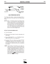
MACHINE COOLING
The fan pulls air in through the louvered front of the
machine over the internal parts and exhausts out the
louvered rear of the machine. The fan motor is fully
enclosed, has sealed ball bearings, requires no lubri-
cation, and operates when the power switch is turned
on.
CASE FEATURES
The machine uses a 32” (813mm) long base. The low
profile case facilitates installation of the machine
under a workbench.
The case front incorporates a recessed control panel
where all the machine controls are mounted. This
recessed panel protects the controls and minimizes
the possibilities of accidental contact. This control
panel can be easily opened to permit access to the
enclosed control section which contains the terminal
strips, PC board, etc.
The output lead terminals are also recessed to avoid
any object or person accidentally coming in contact
with an output terminal. Strain relief is provided by
holes in the front of the base. The leads are routed up
through these holes to the output terminals. This pre-
vents any damage of the output studs or insulation of
same in the event the cables are pulled excessively.
An output stud cover protects against accidental con-
tact with the output studs. Cover hinges upward for
access to the studs.