


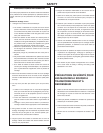
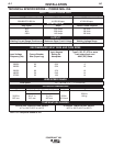
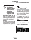
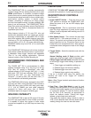
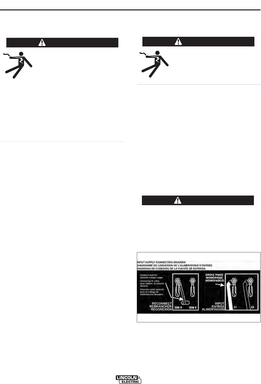
FIGURE A.1 — Dual Voltage Machine Input
Connections
A-2
A-2
INSTALLATION
Read entire installation section before starting
installation.
SAFETY PRECAUTIONS
INPUT POWER, GROUNDING AND
CONNECTION DIAGRAM
1. Before starting the installation, check with the local
power company if there is any question about
whether your power supply is adequate for the volt-
age, amperes, phase, and frequency specified on
the welder rating plate. Also be sure the planned
installation will meet the U.S. National Electrical
Code and local code requirements. This welder
may be operated from a single phase line or from
one phase of a two or three phase line.
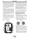
2. Models that have multiple input voltages specified
on the nameplate (e.g. 208/230) are shipped con-
nected for the highest voltage. If the welder is to be
operated on lower voltage, it must be reconnected
according to the instructions in Figure A.1 for dual
voltage machines and Figure A.2 for triple voltage
machines.
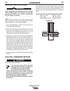
Make certain that the input power is electrically
disconnected before removing the screw on the
reconnect panel access cover.
------------------------------------------------------------------------
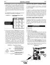
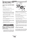
UNCRATING THE POWER MIG
®
256
Cut banding and lift off cardboard carton. Cut banding
holding the machine to the skid. Remove foam and
corrugated packing material. Untape accessories from
Gas Bottle Platform. Unscrew the two wood screws
(at the Gas Bottle Platform) holding the machine to
the skid. Roll the machine off the skid assembly.
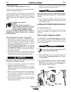
LOCATION
Locate the welder in a dry location where there is free
circulation of clean air into the louvers in the back and
the louvers out the front. A location that minimizes the
amount of smoke and dirt drawn into the rear louvers
reduces the chance of dirt accumulation that can
block air passages and cause overheating.
ELECTRIC SHOCK can kill.
• Only qualified personnel should
perform this installation.
• Only personnel that have read
and understood the POWER MIG
®
256 Operatorʼs Manual should
install and operate this equip-
ment.
• Machine must be grounded per
any national, local or other applic-
able electrical codes.
• The POWER MIG
®
256 power
switch is to be in the OFF posi-
tion when installing work cable
and gun and when connecting
other equipment.
WARNING
WARNING
ELECTRIC SHOCK can kill.
• Do not touch electrically live parts such as
output terminals or internal wiring.
• All input power must be electrically dis-
connected before proceeding.
WARNING
POWER MIG
®
256