


D-2
D-2
MAINTENANCE
5. Fully seat the liner bushing into the connector.
tighten the set screw on the brass cable connector.
The gas diffuser, at this time, should not be
installed onto the end of the gun tube.
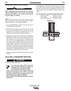
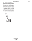
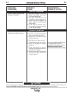
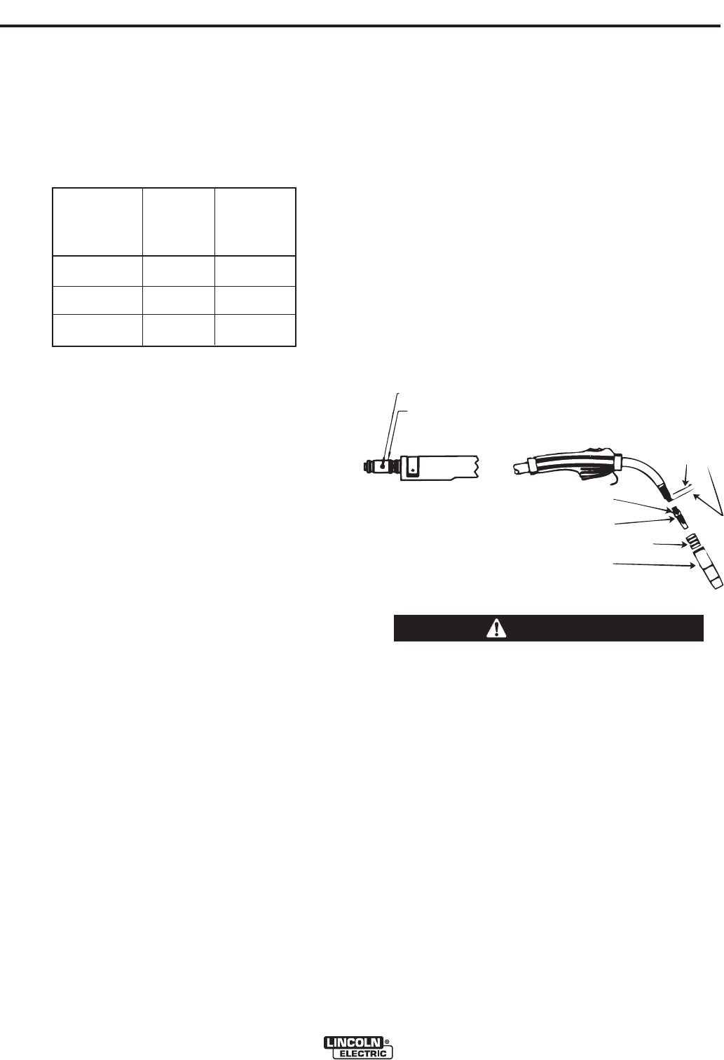
6. With the gas diffuser still removed from the gun
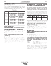
tube, be sure the cable is straight, and then trim
the liner to the length shown in Figure D.1.
Remove any burrs from the end of the liner.
7. Screw the gas diffuser onto the end of the gun tube
and securely tighten.
8. Tighten the set screw in the side of the gas diffuser
against the cable liner using a 5/64" (2.0 mm) Allen
wrench.
FIGURE D.1
This screw should only be gently tightened.
Overtightening will split or collapse the liner and
cause poor wire feeding.
------------------------------------------------------------------------
LINER REMOVAL AND REPLACE-
MENT
NOTE: Changing the liner for a different wire size
requires replacement of the gas diffuser per Table D.1
to properly secure the different liner.
LINER REMOVAL, INSTALLATION
AND TRIMMING INSTRUCTIONS
FOR MAGNUM
®
PRO 250L
NOTE: The variation in cable lengths prevents the
interchangeability of liners between guns. Once a liner
has been cut for a particular gun, it should not be
installed in another gun unless it can meet the liner
cutoff length requirement. Liners are shipped with the
jacket of the liner extended the proper amount.
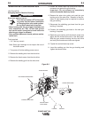
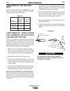
1. Remove the gas nozzle and nozzle insulator, if
used, to locate the set screw in the gas diffuser
which is used to hold the old liner in place. Loosen
the set screw with a 5/64" (2.0 mm) Allen wrench.
2. Remove the gas diffuser from the gun tube.
3. Lay the gun and cable out straight on a flat surface.
Loosen the set screw located in the brass connec-
tor at the feeder end of the cable and pull the liner
out of the cable.
4. Insert a new untrimmed liner into the connector
end of the cable. Be sure the liner bushing is sten-
cilled appropriately for the wire size being used.
Note: For liners KP45-3545-15 and KP45-3545-25
Before fully seating the liner bushing, it will be neces-
sary to trim the linerʼs inner tube flush with the liner
bushing using a sharp blade. After trimming, remove
any burrs from inner tube and insure that the opening
is fully open.
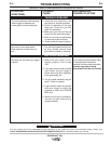
Replacement Size Stencilled
Diameter of Liner Part on End of
Electrodes Used Number Liner Bushing
.025”-.030" Steel KP42-25-15 .030” (0.8 mm)
(0.6-0.8 mm)
.035”-.045" Steel KP42-4045-15 .045” (1.1 mm)
(0.9-1.1 mm)
3/64" Aluminum KP42N-3545-15 3/64" (1.2 mm)
(1.2 mm)
TABLE D.1
SET SCREW
SET SCREW
BRASS CABLE CONNECTOR
GAS DIFFUSER
NOZZLE INSULATOR (IF USED)
GAS NOZZLE
.56"
(14.2mm)
LINER
TRIM
LENGTH
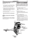
POWER MIG
®
256
CAUTION