


SHIELDING GAS
[For Gas Metal Arc Welding(GMAW) Processes]
Customer must provide cylinder of appropriate type shield-
ing gas for the process being used.
A gas flow regulator, for Argon blend gas, an inlet gas hose,
and a regulator adapter are factory provided with the
POWER MIG
®
256. When using 100% CO
2
, the regulator
adapter will be required to connect the regulator to the gas
bottle.
INSTALL SHIELDING GAS SUPPLY AS FOLLOWS:
1. Set gas cylinder on rear platform of POWER MIG
®
256.
Hook chain in place to secure cylinder to rear of welder.
2. Remove the cylinder cap. Inspect the cylinder valves and
regulator for damaged threads, dirt, dust, oil or grease.
Remove dust and dirt with a clean cloth.
DO NOT ATTACH THE REGULATOR IF OIL, GREASE
OR DAMAGE IS PRESENT! Inform your gas supplier of
this condition. Oil or grease in the presence of high pres-
sure oxygen is explosive.
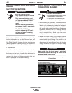
3. Stand to one side away from the outlet and open the
cylinder valve for an instant. This blows away any dust or
dirt which may have accumulated in the valve outlet.
Be sure to keep your face away from the valve
outlet when “cracking” the valve.
--------------------------------------------------------------------------------
4. Attach the flow regulator to the cylinder valve and tighten
the union nut(s) securely with a wrench.
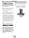
NOTE: If connecting to 100% CO
2
cylinder, the regulator
adapter provided must be installed between the regulator
and cylinder valve.
5. Attach one end of the inlet gas hose to the outlet fitting of
the flow regulator, the other end to the POWER MIG
®
256 rear fitting marked “Feeder” and tighten the union
nuts securely with a wrench.
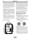
6. Before opening the cylinder valve, turn the regulator
adjusting knob counterclockwise until the adjusting
spring pressure is released.
A-4
A-4
INSTALLATION
7. Standing to one side, open the cylinder valve slowly a
fraction of a turn. When the cylinder pressure gauge
pointer stops moving, open the valve fully.
Never stand directly in front of or behind the flow regu-
lator when opening the cylinder valve. Always stand to
one side.
--------------------------------------------------------------------------------
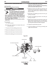
8. The flow regulator is adjustable. Adjust it to the flow rate
recommended for the procedure and process being used
before making the weld.
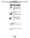
CYLINDER may explode if
damaged.
• Gas under pressure is explosive.
Always keep gas cylinders in an upright
position and always keep chained to
undercarriage or stationary support.
See American National Standard Z49.1, “Safety in
Welding and Cutting” published by the American
Welding Society.
------------------------------------------------------------------------
WARNING
WARNING
POWER MIG
®
256
AUXILIARY POWER RECEPTACLES
(For 208/230V Models only)
This machine is equipped with 15Amp 120V receptacle with
15Amp Circuit Breaker. The receptacle is UL and CSA
approved.
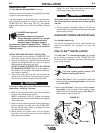
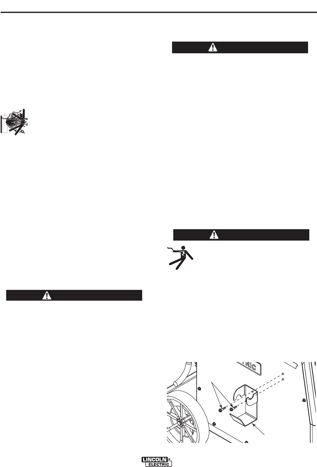
COIL CLAW™ INSTALLATION
The Coil Claw™ and mounting screws are provided
as an optional accessory for the
POWER MIG
®
256
.
This user-install accessory provides cable manage-
ment for the machine.
Turn the welder power switch OFF
before installing Coil Claw™.
------------------------------------------------------------------------
1. Unwrap Coil Claw™ from its protective paper and
remove the bag of mounting screws from the back
of the Coil Claw™.
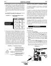
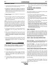
2. Mount the Coil Claw™ using the provided
mount-
ing screws to the left side of the machine, when
viewed from the front. Make sure the Coil Claw™ is
firmly mounted. (See Figure A.5)
FIGURE A.5
MOUNTING
SCREWS
COIL CLAW™
WARNING