


3
2
1
4
5
6
7
8
B-3
B-3
OPERATION
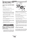
To make spot plug welds, punch 3/16" (5 mm) holes
in the top sheet. Set the Spot Time control to
approximately 1.2 seconds and set the procedure for
the metal thickness to be welded. Install spot weld
nozzle (if available) on gun and press it against the
top sheet so the top and bottom sheets are tight
together. Close trigger and hold it closed until the arc
goes out. If a spot weld nozzle is not used, smoother
welds will result by moving the welding wire in a
small circle during the weld.
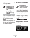
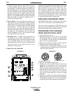
6. Run-In Mode - is used to adjust the starting wire
feed speed. Starting conditions for certain welding
applications can be improved with adjustment to the
Run-In speed. The control allows for initial starting
speeds from 50 - 150 IPM. After the arc is started,
the set point on the wire feed speed control will
dominate. Note that the Run-in is not functional with
the spool gun. Also note that if Run-in is set fully
counter clockwise to "OFF", Run-in speed will equal
the preset WFS on the machine.
7. Burnback Time - Provides manual adjustment of
the burnback time (0-250 milliseconds) for any
selected welding mode. this control should be set as
low as possible without the wire "sticking" in the
puddle after each weld. Too long of a burnback time
may form a "ball" on the end of the wire, or may
"flash back" to the gun tip.
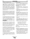
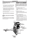
8. Spool Gun Gas Connection
FIGURE B.1
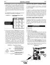
The drive rolls installed with the POWER MIG® 256
have two grooves one for .035(0.9mm) wire Solid
Steel electrode and the other for .045(1.1mm) wire.
Drive roll size is stenciled on each side of the drive
roll. If feeding problems occur, check to make sure
that the wire size and the drive roll size matches. See
"Procedure for Changing Drive Roll" in this section.
This information also appears on the Procedure Decal
on the door inside the wire compartment.
WIRE SIZE CONVERSION PARTS
The POWER MIG® 256 is rated to feed .025 through
.045" (0.6-1.1 mm) solid or cored electrode sizes.
The drive roll kits and Magnum
®
PRO 250L gun and
cable parts are available to feed different sizes and
types of electrodes. See Accessories section.
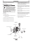
PROCEDURE FOR CHANGING
DRIVE AND IDLE ROLL SETS
1. Turn off the power source.
2. Release the pressure on the idle roll by swinging
the adjustable pressure arm down toward the back
of the machine. Lift the cast idle roll assembly and
allow it to sit in an upright position.
3. Remove the outside wire guide retaining plate by
loosening the two large knurled screws.
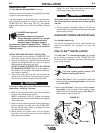
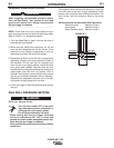
4. Twist the drive roll retaining mechanism to the
unlocked position as shown below and remove the
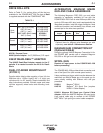
drive roll. (See Figure B.2)
FIGURE B.2
5. Remove the inside wire guide plate.
6. Replace the drive and idle rolls and inside wire
guide with a set marked for the new wire size.
NOTE: Be sure that the gun liner and contact tip
are also sized to match the selected wire size.
7. Manually feed the wire from the wire reel, over the
drive roll groove and through the wire guide and
then into the brass bushing of the gun and cable
assembly.
8. Replace the outside wire guide retaining plate by
tightening the two large knurled screws. Reposition
the adjustable pressure arm to its original position
to apply pressure. Adjust pressure as necessary.
LOCKED POSITION
UNLOCKED POSITION
POWER MIG
®
256