


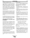
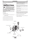

Hand Screw
Male End
Gun and Cable
Gun Adapter
Receptacle
Gun Trigger
Connector
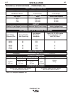
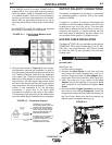
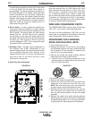
3. The 208/230 volt 60 Hz model POWER MIG is
shipped with a 10 ft. input cable and plug connect-
ed to the welder. Obtain a receptacle and mount it
in a suitable location. Be sure it can be reached by
the plug on the input cable attached to the welder.
Mount with the grounding terminal at the top to
allow the power cable to hang down without bend-
ing.
The 230/460/575 volt 60 Hz model is not equipped
with a plug, an input cable or a receptacle.
FIGURE A.2 — Triple Voltage Machine Input
Connection
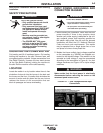
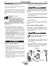
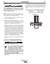
4. Using the instructions in Figure A.3, have a quali-
fied electrician connect the receptacle or cable to
the input power lines and the system ground per the
U.S. National Electrical Code and any applicable
local codes. See "Technical Specifications" at the
beginning of this chapter for proper wire sizes. For
long runs over 100 feet, larger copper wires should
be used. Fuse the two hot lines with super lag type
fuses as shown in the following diagram. The center
contact in the receptacle is for the grounding
connection. A green wire in the input cable
connects this contact to the frame of the welder.
This ensures proper grounding of the welder frame
when the welder plug is inserted into the receptacle.
A-3 A-3
INSTALLATION
OUTPUT POLARITY CONNECTIONS
The welder, as shipped from the factory, is connected
for electrode positive (+) polarity. This is the normal
polarity for GMAW.
If negative (–) polarity is required, interchange the
connection of the two cables located in the wire drive
compartment near the front panel. The electrode
cable, which is attached to the wire drive, is to be con-
nected to the negative (–) labeled terminal and the
work lead, which is attached to the work clamp, is to
be connected to the positive (+) labeled terminal.
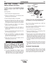
GUN AND CABLE INSTALLATION
The
Magnum
®
PRO
250L gun and cable provided with the
POWER MIG
®
256 is factory installed with a liner for .035-
.045" (0.9-1.1 mm) electrode and an .035" (0.9 mm) contact
tip.
Install the .045” tip (also provided) if this wire size
is being used.
Turn the welder power switch off before installing
gun and cable.
(See Figure A.4)
1. Lay the cable out straight.
2. Unscrew the Hand Screw on the drive unit front
end (inside wire feed compartment) until tip of
screw no longer protrudes into Gun Adapter open-
ing as seen from front of machine. (See Figure A.4)
3. Insert the male end of gun cable into the Gun
Adapter through the opening in front panel. Make
sure connector is fully inserted and tighten Hand
Screw.
4. Connect the Gun Trigger Connector from the gun
and cable to the mating Receptacle inside the
compartment located left just inside the opening on
the Front Panel. Make sure that the keyways are
aligned, insert and tighten retaining ring.
POWER MIG
®
256
FIGURE A.3 —Receptacle Diagram
CONNECT TO A SYSTEM
GROUNDING WIRE. SEE THE
UNITED STATES NATIONAL
ELECTRICAL CODE AND/OR
LOCAL CODES FOR OTHER
DETAILS AND MEANS FOR
PROPER GROUNDING.
CONNECT TO HOT WIRES OF
A THREE-WIRE, SINGLE
PHASE SYSTEM OR TO ONE
PHASE OF A TWO OR
THREE PHASE SYSTEM.
WARNING
FIGURE A.4