


CONTROL CABLE CONNECTIONS
BETWEEN POWER SOURCE AND
WIREFEEDER
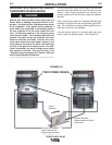
Connect the control cable between the power source
and wire feeder. The wire feeder connection on the
PowerWave AC/DC is located under the spring loaded
output cover, on the case front. The control cable is
keyed and polarized to prevent improper connect.
For convenience, the control cables can be routed
behind the left or right strain relief (under the spring
loaded output cover), along the channels of the Power
Wave, out the back of the channels, and then to the
wire feeder.
Excessive voltage drops at the work piece con-
nection often result in unsatisfactory pulse weld-
ing performance.
------------------------------------------------------------------------
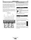
CONTROL CABLE CONNECTIONS
BETWEEN POWER SOURCES RUN
IN PARALLEL
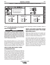
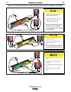
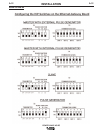
The connectors located on the rear of the machine are
used for synchronizing the operation of multiple
machines. To run machines in parallel connect the
control cable (K1795 series) between power sources
that are to run in parallel. The bottom (male) connec-
tor on the master connects to the top (female) connec-
tor on the slave. If needed the bottom connector on
the slave machine is then used to connect to another
slave machine. This connection scheme is duplicated
for any additional slaves.
CONTROL CABLE CONNECTIONS
BETWEEN A POWER SOURCE
AND PHASE GENERATOR
If multiple arcs need to be synchronized an external
phase generator is required. The phase generator is
connected to all of the master machines. A control
cable (K1795 series) should be connected between
the phase generator and the top (female) connector
on the rear of the master machine.
CONTROL CABLE SPECIFICATIONS
It is recommended that genuine Lincoln control cables
be used at all times. Lincoln cables are specifically
designed for the communication and power needs of
the Power Wave / Power Feed system.
The use of non-standard cables, especially in
lengths greater than 25 feet, can lead to communi-
cation problems (system shutdowns), poor motor
acceleration (poor arc starting) and low wire dri-
ving force (wire feeding problems). Use the short-
est length of control cable possible. Do not coil
excess cable as this can cause communication
problems (system shutdowns).
------------------------------------------------------------------------
Lincoln control cables are copper 22 conductor cable
in a SO-type rubber jacket.
The K1795 series of control cables can be added in
series as needed. Do not exceed more than 100 feet
(30.5 m) total control cable length.
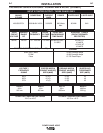
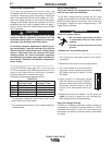
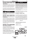
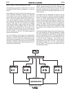
ETHERNET CONNECTIONS
The PowerWave is equipped with an Ethernet con-
nector, which is located under the spring loaded out-
put cover. All Ethernet cables external to either a con-
duit or an enclosure should be solid, shielded with a
drain, cat 5 cable. The drain should be grounded. Do
not use cat 5+, cat 5E, cat 6 or stranded cable. If con-
nection failure during welding persists reroute cables
away from any other cables that carry current or other
devices that would create a magnetic field. See Figure
A.4a.
FIGURE A.4a
CAUTION
CAUTION
A-8
INSTALLATION
POWER WAVE AC/DC
A-8
POWER WAVEPOWER WAVEPOWER WAVE
POWER WAVE POWER WAVE
PHASE
GENERATOR
CAT 5 CABLE
SOLID, SHIELDED,
WITH A DRAIN
(MAX LENGTH =
3 METERS)
JUNCTION BOX
CONDUIT WITH CAT 5 UTP CABLE
ENVIRONMENTAL
ENCLOSURE
ETHERNET SWITCH
PATCH PANEL
POWER WAVE ETHERNET LAYOUT SETUP
- MAX TOTAL CABLE LENGTH IS 70 METERS
(FROM POWER WAVE TO PATCH PANEL)
- SHIELDED CABLE SHOULD BE GROUNDED
AT JUNCTION BOX
- REFER TO ISO / IEC 11801 FOR SPECIFICATIONS