


B-6
OPERATION
B-6
POWER WAVE AC/DC
Second, find the program in the welding software that
best matches the desired welding process. The stan-
dard software shipped with the Power Waves encom-
passes a wide range of common processes and will
meet most needs. If a special welding program is
desired, contact the local Lincoln Electric sales repre-
sentative.
To make a weld, the Power Wave needs to know the
desired welding parameters. ArcLink allows full cus-
tomization for exacting performance. The Power
Wave can be programmed with specific values for
Strike, Run-in, Crater and other parameters as need-
ed.
The Power Wave supports advanced features, like
touch sensing and through-the-arc-seam tracking
(TAST).
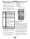
WELDING ADJUSTMENTS
All adjustments are made on through the user inter-
face which can vary. Because of the different configu-
ration options your system may not have all of the fol-
lowing adjustments. Regardless of availability, all con-
trols are described below.
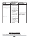
GENERAL WELDING ADJUSTMENTS
1. WFS / AMPS:
In synergic welding modes (synergic CV, pulse
GMAW) WFS (wire feed speed) is the dominant
control parameter, controlling all other variables.
The user adjusts WFS according to factors such as
weld size, penetration requirements, heat input, etc.
The Power Wave then uses the WFS setting to
adjust its output characteristics (output voltage, out-
put current) according to pre-programmed settings
contained in the Power Wave. In non-synergic
modes, the WFS control behaves more like a con-
ventional CV power source where WFS and voltage
are independent adjustments. Therefore to maintain
the arc characteristics, the operator must adjust the
voltage to compensate for any changes made to the
WFS.
2. VOLTS / TRIM:
In constant voltage modes (synergic CV, standard
CV) the control adjusts the welding voltage.
In pulse synergic welding modes (pulse GMAW
only) the user can change the Trim setting to adjust
the arc length. It is adjustable from 0.500 to 1.500.
A Trim setting of 1.000 is a good starting point for
most conditions.
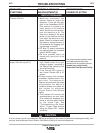
3. WELDING MODE:
May be selected by name (CV/MIG, CC/Stick Crisp,
Gouge, etc.) or by a mode number (10, 24, 71,
etc.). Selecting a welding mode determines the out-
put characteristics of the Power Wave power
source
4. ARC CONTROL:
Also known as Inductance or Wave Control. Allows
operator to vary the arc characteristics from "soft" to
"harsh" in all weld modes. It is adjustable from -10.0
to +10.0, with a nominal setting of 0.0.