


B-5
OPERATION
POWER WAVE AC/DC
B-5
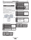
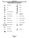
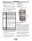
CASE FRONT CONTROLS
All operator controls and adjustments are located on
the case front of the Power Wave. (See Figure B.1)
1. POWER SWITCH: Controls input power to the
Power Wave.
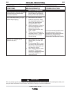
2. STATUS LIGHT: A two color light that indicates
system errors. Normal operation is a steady green
light. Error conditions are indicated per table B1.
NOTE: The robotic PowerWaves’ status light will flash
green, for up to 15 seconds when the machine is first
turned on. This is a normal situation as the machine
goes through a self test at power up.
TABLE B1
Light
Condition
Steady Green
Blinking
Green
Alternating
Green and
Red
Steady Red
Blinking Red
Meaning
System OK. Power source communicating normal-
ly with wire feeder and its components.
Occurs during a reset, and indicates the PW-
AC/DC is mapping (identifying) each compo-
nent in the system. Normal for first 1-10 sec-
onds after power is turned on, or if the system
configuration is changed during operation.
Non-recoverable system fault. If the PS
Status light is flashing any combination of
red and green, errors are present in the PW-
AC/DC. Read the error code before the
machine is turned off.
Error Code interpretation through the Status
light is detailed in the Service Manual.
Individual code digits are flashed in red with
a long pause between digits. If more than
one code is present, the codes will be sepa-
rated by a green light.
To clear the error, turn power source off, and
back on to reset. See Troubleshooting
Section.
Not applicable.
Not applicable.
6. LEAD CONNECTOR S2 (SENSE LEAD)
7. 5-PIN ARC LINK S1
8. 5-PIN DEVICENET CONNECTOR S5
9. I / O CONNECTOR
10. NEGATIVE STUD
11. INTERFACE CONNECTOR S6
12. POSITIVE STUD
13. AUXILUARY OUTPUT
14. ETHERNET CONTROLS (NOT SHOWN)
FIGURE B.1
3. HIGH TEMPERATURE LIGHT (thermal overload):
A yellow light that comes on when an over temper-
ature situation occurs. Output is disabled until the
machine cools down. When cool, the light goes out
and output is enabled.
4. 10 AMP WIRE FEEDER CIRCUIT BREAKER:
Protects 40 volt DC wire feeder power supply.
5.
AUXILIARY POWER CIRCUIT BREAKER:
Protects
case front receptacle auxiliary supply. (10 amp on
non-CE models, 5 amp on CE models.)
WELDER OPERATION
Making a Weld
The serviceability of a product or structure utilizing the
welding programs is and must be the sole responsibili-
ty of the builder/user. Many variables beyond the con-
trol of The Lincoln Electric Company affect the results
obtained in applying these programs. These variables
include, but are not limited to, welding procedure,
plate chemistry and temperature, weldment design,
fabrication methods and service requirements. The
available range of a welding program may not be suit-
able for all applications, and the build/user is and must
be solely responsible for welding program selection.
The steps for operating the Power Wave will vary
depending upon the user interface of the welding sys-
tem. The flexibility of the Power Wave lets the user
customize operation for the best performance.
First, consider the desired welding process and the
part to be welded. Choose an electrode material,
diameter, shielding gas and process (GMAW, GMAW-
P, SAW, etc.)