


vi
vi
TABLE OF CONTENTS
Page
Installation .......................................................................................................Section A
Technical Specifications - POWER WAVE AC/DC ...............................................A-1
Safety Precautions.................................................................................................A-2
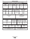
Select Suitable Location ........................................................................................A-2
Lifting...............................................................................................................A-2
Stacking ..........................................................................................................A-2
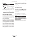
Machine Grounding ...............................................................................................A-2
High Frequency Protection ....................................................................................A-2
Input Connection....................................................................................................A-3
Input Fuse and Supply Wire Considerations .........................................................A-3
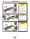
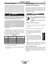
Input Voltage Changeover Procedure ...................................................................A-3
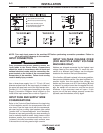
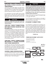
Welding with Multiple Power Waves......................................................................A-4
Multiple Arc Configuration ...............................................................................A-5
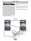
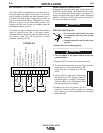
Electrode and Work Cable Connections................................................................A-6
Cable Inductance and its Effects on Pulse Welding........................................A-6
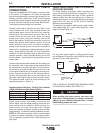
Voltage Sensing .............................................................................................A-7
Control Cable Connections Between Power Source and Wirefeeder....................A-8
Control Cable Connections Between Power Sources Run in Parallel...................A-8
Control Cable Connections between a Power Source and Phase Generator......A-8
Control Cable Specifications, Ethernet Connections.............................................A-8
External I/O Connector....................................................................................A-9
High Speed Gear Box .....................................................................................A-9
Dip Switch Settings and Locations...............................................................A-10
Control Board Dip Switch..............................................................................A-10
Feed Head Board Dip Switch........................................................................A-10
DeviceNET/Gateway Board Dip Switch, .......................................................A-11
Multiple-Arc System Description ...................................................................A-12
________________________________________________________________________
Operation .........................................................................................................Section B
Safety Precautions.................................................................................................B-1
Graphic Symbols that appear on this machine or in this manual...........................B-2
Definiition of Welding Terms..................................................................................B-3
General Description...............................................................................................B-4
Recommended Processes and Equipment ...........................................................B-4
Required Equipment..............................................................................................B-4
Limitations..............................................................................................................B-4
Duty Cycle and Time Period ...........................................................................B-4
Case Front Controls........................................................................................B-5
Constant Voltage Welding...............................................................................B-6
Pulse Welding .................................................................................................B-7
________________________________________________________________________
Accessories.....................................................................................................Section C
Optional Equipment...............................................................................................C-1
Factory Installed..............................................................................................C-1
Field Installed..................................................................................................C-1
________________________________________________________________________
Maintenance ....................................................................................................Section D
Safety Precautions ................................................................................................D-1
Routine, Periodic, Calibration Specification...........................................................D-1
________________________________________________________________________
Troubleshooting..............................................................................................Section E
How to use Troubleshooting Guide .......................................................................E-1
Troubleshooting the Power Wave / Power Feed System using the Status LED ...E-2
Troubleshooting Guide.............................................................................E-3 thru E-6
Error Codes for the Power Wave ...................................................................E-7, E-8
________________________________________________________________________
Diagrams ..........................................................................................................Section F
Wiring Diagram ......................................................................................................F-1
Pin, Lead Connector, Connection Diagrams, and Dimension Print..........F-2 thru F-5
________________________________________________________________________
Parts Lists................................................................................................................P392