


A-10
INSTALLATION
POWER WAVE AC/DC
A-10
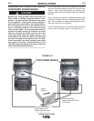
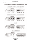
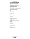
DIP Switch Settings and Locations
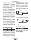
DIP switches on the P.C. Boards allow for custom
configuration of the Power Wave. To access the DIP
switches:
• Turn off power at the disconnect switch.
------------------------------------------------------------------------
• Remove the top four screws securing the front
access panel.
• Loosen, but do not completely remove, the bottom
two screws holding the access panel.
• Open the access panel, allowing the weight of the
panel to be carried by the bottom two screws. Make
sure to prevent the weight of the access panel from
hanging on the harness.
• Adjust the DIP switches as necessary.
• Replace the panel and screws, and restore power.
WARNING
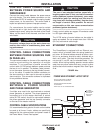
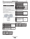
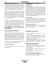
CONTROL BOARD DIP SWITCH
Switch Description Comments
1 Object Instance LSB (see table A.3)
2 Object Instance MSB (see table A.3)
3 Equipment Group 1 Select
4 Equipment Group 2 Select Used for ArcLink
5 Equipment Group 3 Select configuration
6 Equipment Group 4 Select
7 Reserved for future use
Used for configuring
work sense lead
(See Work Volktage
Sensing in Section A)
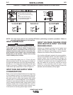
OBJECT INSTANCE
switch 2 switch 1 Instance
off off 0
off on 1
on off 2
on on 3
TABLE A.3
(default)
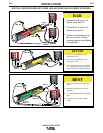
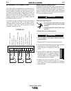
FEED HEAD BOARD DIP SWITCH:
Switch Description Comments
1 Object Instance LSB (see table A.3)
2 Object Instance MSB (see table A.3)
3 Equipment Group 1 Select
4 Equipment Group 2 Select
Used for ArcLink Configuration
5 Equipment Group 3 Select
6 Equipment Group 4 Select
Used for configuring electrode
polarity (see Electrode and Work
7
Cable Connection in this Section)
No changes required for Power
Wave AC/DC
Used for configuring wirefeeder
8
gear ratio (see High Speed Gear
Box in this Section)
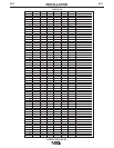
Bank S1
Switch Description Comments
1 Object Instance LSB (see table A.3)
2 Object Instance MSB (see table A.3)
3 Equipment Group 1 Select
4 Equipment Group 2 Select
Used for ArcLink Configuration
5 Equipment Group 3 Select
6 Equipment Group 4 Select
7 Reserved for future use
8 Reserved for future use
Bank S2:
Switch Description Comments
1 DeviceNet Baud Rate
2 (See Table A.4)
3
4
Used for DeviceNet
5 DeviceNet Mac ID
Configuration
6 (See Table A.5)
7
8
ETHERNET BOARD DIP SWITCH:
DeviceNet Baud Rate:
switch 1 switch 2 Baud rate
off off 125K
on off 250K
off on 500K
on on Programmable value
TABLE A.4
off work sense lead not connected
on work sense lead connected
8
off Electrode polarity positive (default)
on Electrode polarity negative
off Low speed gear (default)
on High speed gear