


A-3
INSTALLATION
A-3
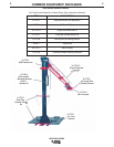
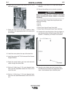
10. Install with arm section with the six 1/2" x 1-1/4
bolts and washers.
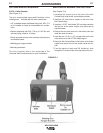
11. Raise the front of the arm with a forklift or hoist
and attach to the appropriate hole in the clevis and
arm triangle.
12. Install the cover plate at the top of the stanchion.
13. Install the optional K1779-9 Universal Wire Feeder
Support Bracket.
14. Route the control cable, gas hose and electrode
cable through the center tube.
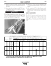
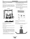
15. Slip the 3' (0.9m) long, 2" (51 mm) diameter black
hose over the assembled cables and hose at the
rear of the arm.
16. Slip the 1' (0.3m) long, 2" (51 mm) diameter black
hose over the assembled cables at the front of the
arm.
WELDING ARMS
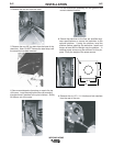
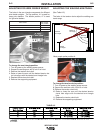
17. Slip the 4" (102 mm) of PVC tube over the gas
hose(s).
18. Secure the welding arm to prevent movement.
Secure the welding arm to prevent movement
before mounting wire feeder, cables, or any other
accessory.
------------------------------------------------------------------------
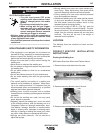
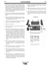
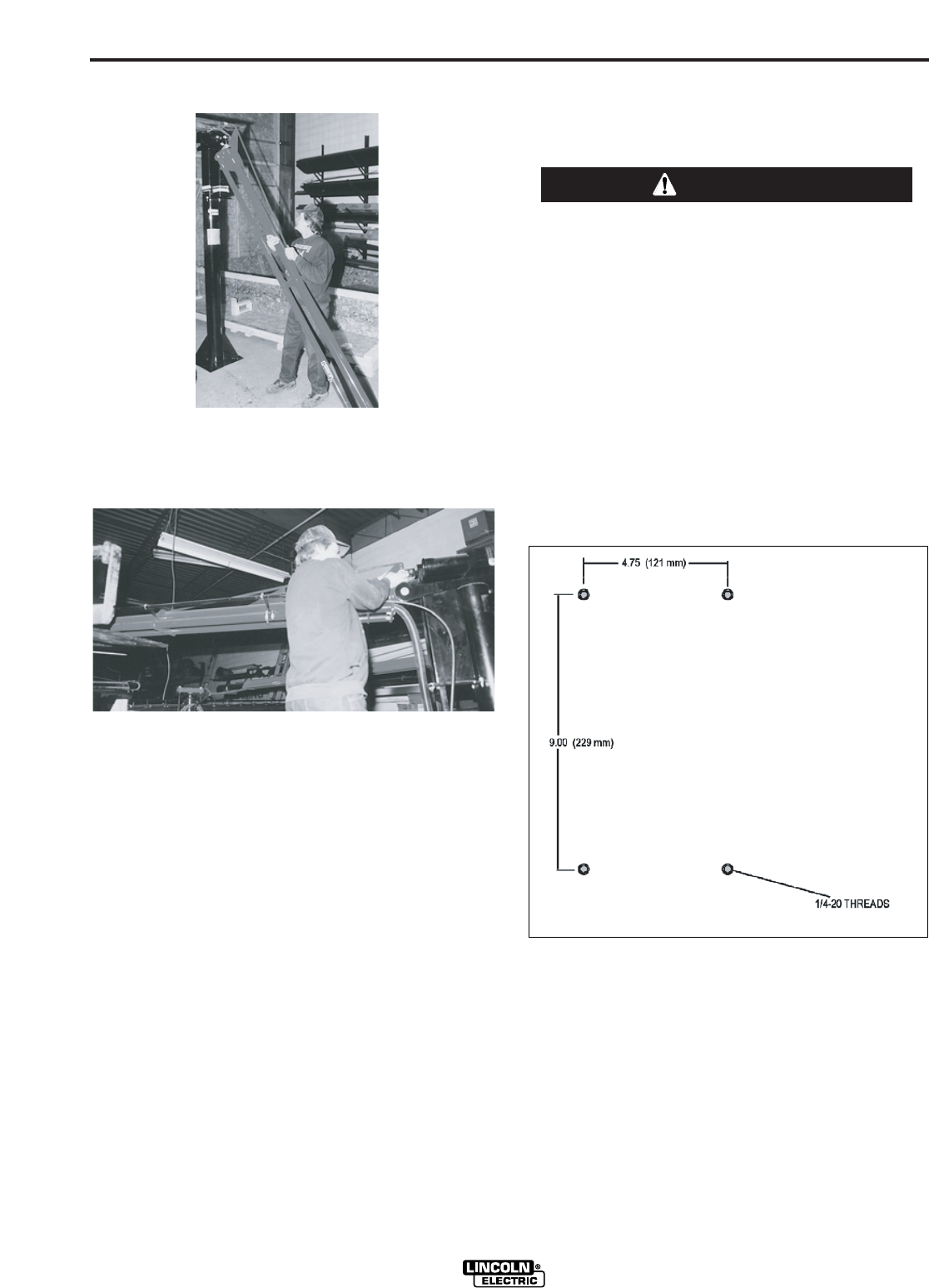
The Universal Wire Feeder Mounting Bracket has
holes for mounting:
• LF-72
• LN-10
• DH-10
• Power Feed 10 and Power Feed 10M
• Power Feed 10 Dual and Power Feed 10M Dual
19. Compare the mounting holes of the wire feeder to
the mounting holes on the Universal Wire Drive
Bracket. If necessary, drill holes in the bracket.
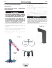
20. Place the wire feeder onto the Universal Wire
Drive Bracket and attach with appropriate hard-
ware. Use hardware that is vibration proof.
WARNING